Technical Specifications:
Brand: Yaskawa
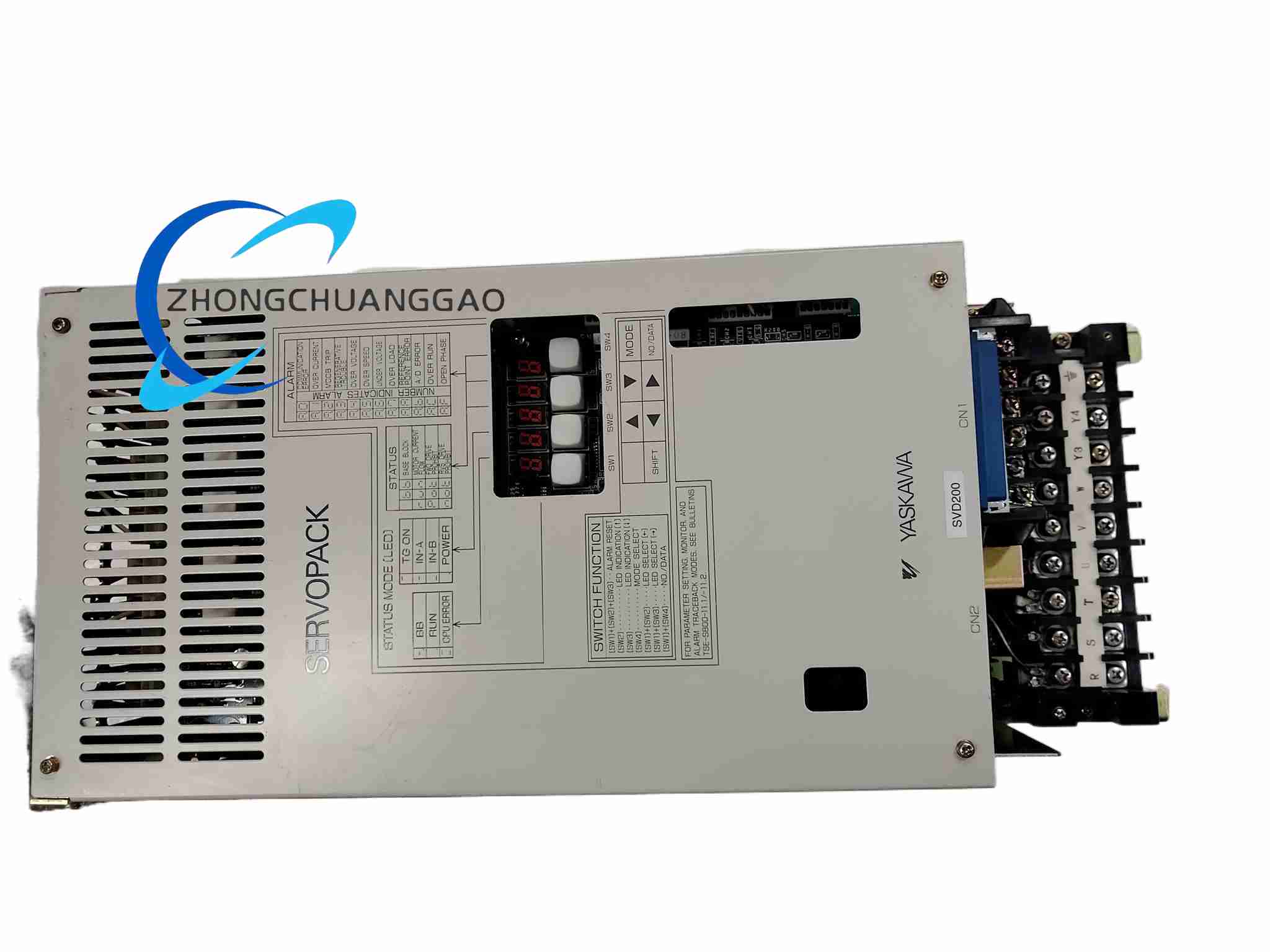
Model: CACR-SR60BE12D-CY119
Configured Series: Sigma 7 compatible configuration records; CACR-SR high-power platform
Rated Power: 6 kW
Input Voltage: Three-phase 200 VAC to 230 VAC, 50/60 Hz
Rated Output Current: 60 A in standard model designation; selected technical records list 45 A continuous and 80.6 A peak
Control Modes: Position, speed, torque
Encoder Feedback: Incremental encoder and absolute encoder
Communication Interfaces: RS-485 Modbus RTU, pulse input, analog input; selected records also list RS-232 or CANopen according to controller configuration
Protection Functions: Overcurrent, overvoltage, undervoltage, overload, overtemperature, encoder error and short-circuit protection
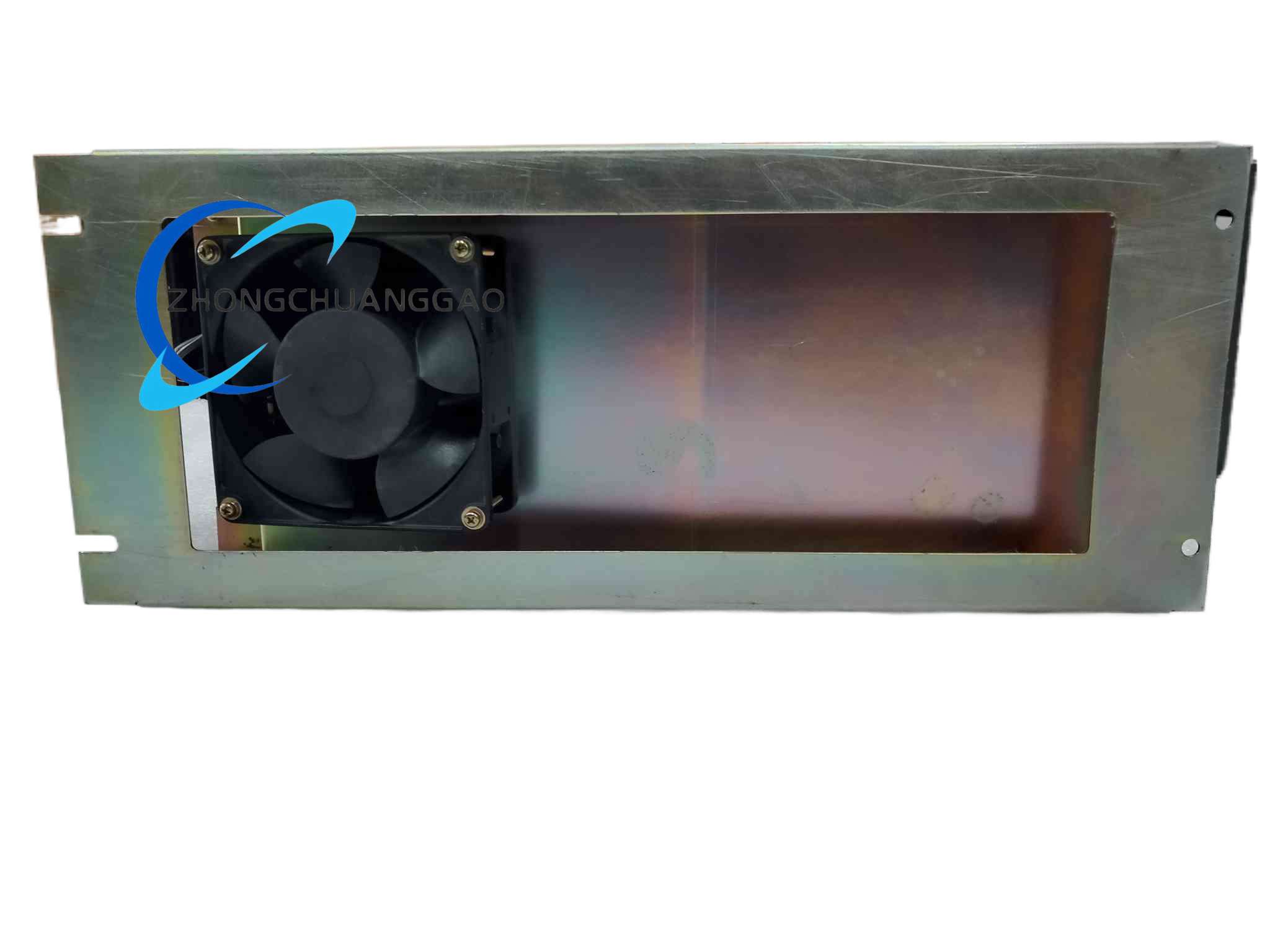
Cooling: Forced-air cooling with internal fan
Protection Rating: IP20
Operating Temperature: 0°C to 55°C
Mounting: Panel mount or cabinet mounting
Functional Features:
Three-Loop Control: Current, speed and position closed loops with high dynamic response
High-Power Output: Suitable for heavy acceleration, high-inertia loads and continuous duty
Communication Flexibility: Modbus RTU, pulse train or analog command integration
Diagnostics: Front operator panel, digital display and alarm codes
Application Scenarios: CNC machine tool axes, heavy robotic joints, injection molding machines, large packaging lines, laser cutting equipment, semiconductor handling systems and other high-power precision automation platforms.
Performance Parameters:
Positioning Accuracy: Determined by Sigma servo motor encoder resolution and control configuration
Current Response: High-bandwidth current loop for rapid torque changes
Overload Capacity: Short-duty peak current according to drive version and cooling condition
Material Composition:
Chassis: Cold-rolled steel cabinet frame
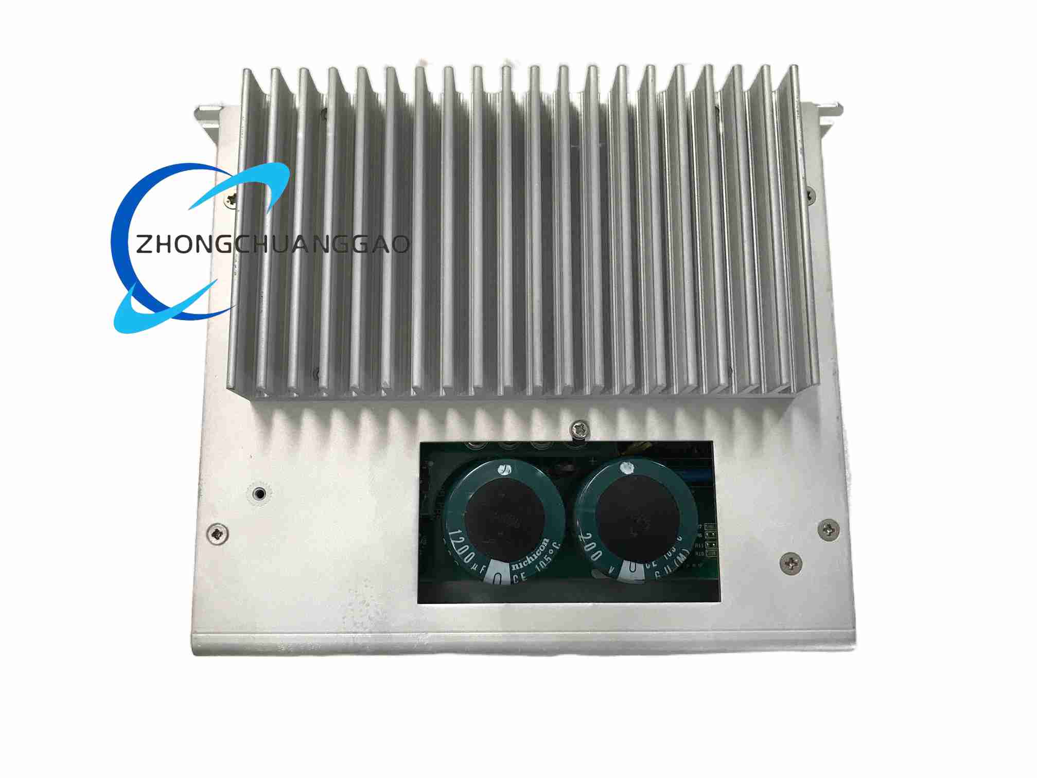
Heatsink: Aluminum alloy fins
Power Module: High-current IGBT inverter modules
Bus Capacitor: High-voltage electrolytic DC-link capacitors
Fan System: Axial forced-cooling fan
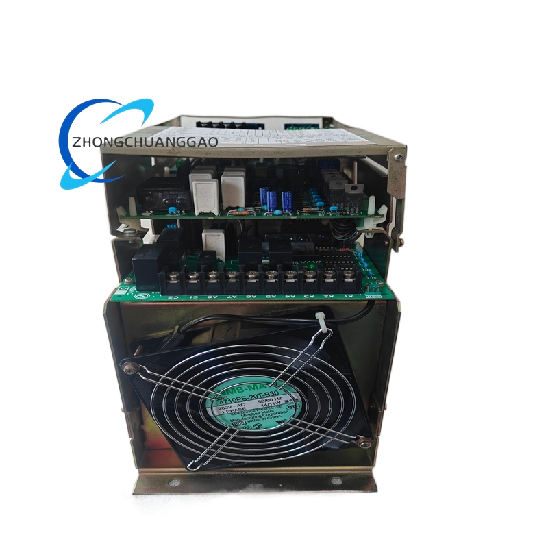
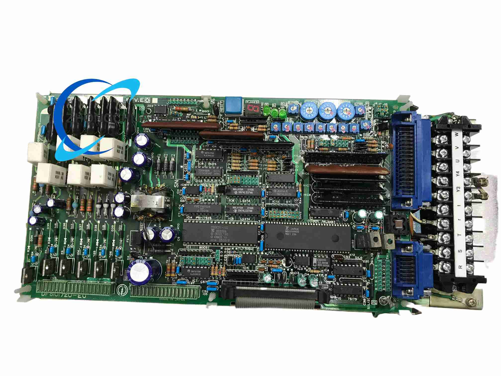
Structural Features: Vertical metal enclosure, front display and status indicators, lower high-current power terminals, upper control and encoder terminals, separated main circuit and signal sections, rear or side cooling air path.
Working Principle: Three-phase AC input is rectified and filtered into a DC bus. The IGBT inverter converts DC into regulated three-phase output according to the control mode. Encoder feedback provides rotor position and speed data for current, speed and position correction. Communication, pulse or analog interfaces receive setpoints from the host controller, and protection circuits disable output during fault conditions.
Installation Requirements: Mount on a rigid cabinet panel with adequate load capacity. Provide top and bottom airflow clearance for the cooling fan. Supply three-phase 200 VAC to 230 VAC through appropriately sized breakers and conductors. Use shielded encoder cables and segregated motor power cables. Establish a low-resistance safety ground connection.
Usage Notes: Pair the drive with a compatible 6 kW class servo motor and matching encoder type. Complete parameter setup, motor autotuning and no-load trial before production. Allow DC-link capacitors to discharge fully before maintenance. Inspect fan operation, terminal heating and cooling passages regularly.