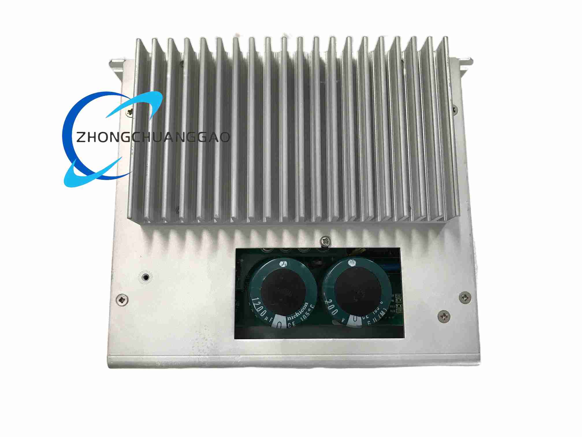
Technical Specifications:
Brand: Yaskawa
Model: CACR-SR20TB0BM
Series: CACR-SR
Rated Power: 2.0 kW
Input Voltage: Three-phase 200 VAC to 240 VAC, 50/60 Hz
Rated Output Current: Configuration dependent; common records list 11 A, 18.8 A or equivalent 2.0 kW drive current
Control Modes: Position, speed, torque
Command Interfaces: Pulse train and ±10 V analog; Mechatrolink-II versions available according to suffix configuration
Encoder Feedback: Incremental encoder; absolute encoder supported on selected variants
Regenerative Braking: Internal braking transistor or internal resistor according to version; external resistor terminal provided on supported models
Speed Response: Approximately 600 Hz to 1.5 kHz depending on firmware and control mode
Protection Rating: IP20
Operating Temperature: 0°C to 45°C for Mechatrolink versions; 0°C to 50°C or wider according to analog/pulse variant
Mounting: Panel mount, vertical cabinet installation
Functional Features:
Dual Command Support: Analog ±10 V and pulse train for PLC or CNC integration
Network Option: Mechatrolink-II deterministic communication on configured versions
Braking Energy Management: Internal regen circuit with external resistor expansion
Protection Functions: Overcurrent, overvoltage, undervoltage, overload, overtemperature, encoder error and regenerative fault protection
Application Scenarios: Packaging machines, printing rollers, material handling transfers, stamping automation, injection molding auxiliaries, palletizing axes and medium-load reciprocating motion systems.
Performance Parameters:
Positioning Accuracy: Defined by encoder resolution, pulse input frequency and mechanical transmission
Speed Range: Wide ratio from low creep speed to rated motor speed
Overload Capacity: Short-duty peak current according to selected drive current rating
Material Composition:
Housing: Cold-rolled steel or coated metal enclosure on selected versions; aluminum fin heatsink
Power Module: High-power IGBT inverter
Control Board: Multilayer FR-4 with EMC filtering
Cooling: Natural convection, fin heatsink or fan-assisted cooling according to variant
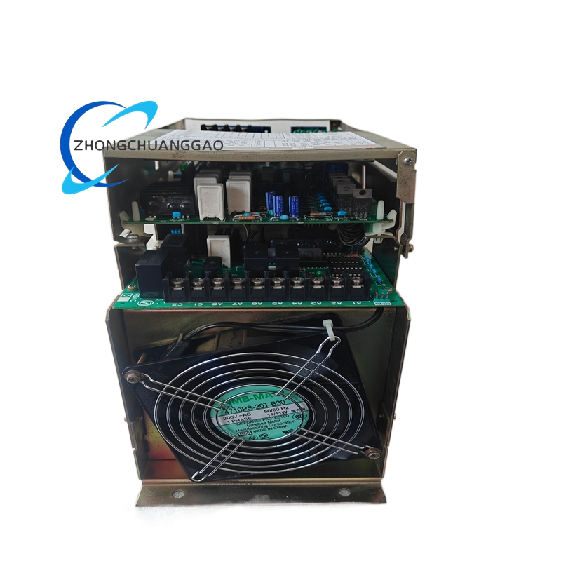
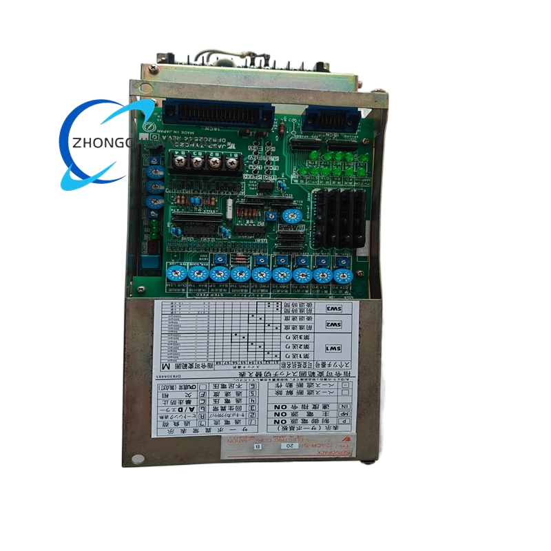
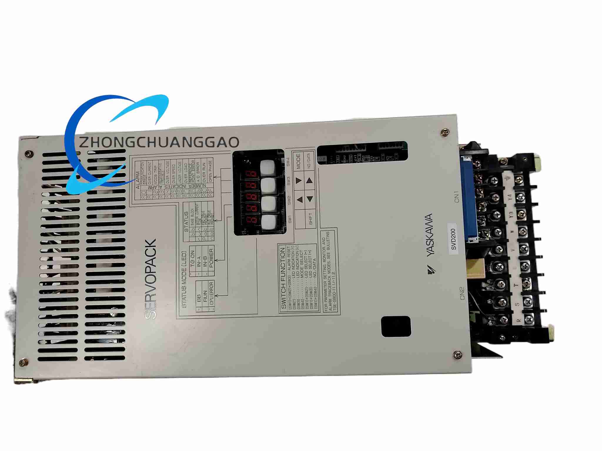
Structural Features: Vertical-mount servo unit, front status LEDs or operator panel, separated power terminal block, encoder connector, control signal terminals, regenerative resistor terminal and network optical port on Mechatrolink versions.
Working Principle: Three-phase AC input passes through EMC filtering and rectification to produce a DC bus. The inverter stage generates PWM three-phase output according to position, speed or torque commands. Encoder feedback closes the servo loops. During deceleration, regenerative energy is absorbed by the internal transistor and resistor network, or diverted to an external resistor.
Installation Requirements: Mount vertically in a ventilated cabinet with top and bottom clearance; Mechatrolink versions require approximately 100 mm top clearance, analog/pulse versions require at least 60 mm depending on cooling design. Supply three-phase 200 VAC to 240 VAC through a properly sized breaker. Use shielded motor power and encoder cables. Separate power and signal routes.
Usage Notes: Confirm whether the unit is analog/pulse or Mechatrolink before installation because command wiring differs. Perform motor parameter autotuning before load operation. Validate braking resistor sizing for high-inertia or frequent deceleration. Inspect cooling fan, filters and terminals on a scheduled basis.