")

Overview:
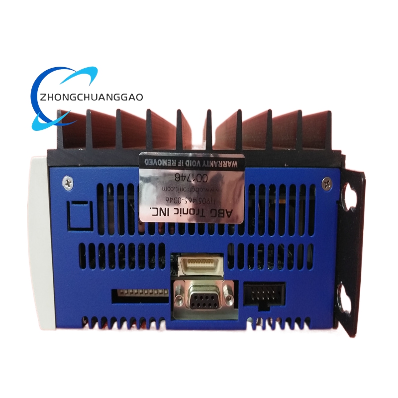
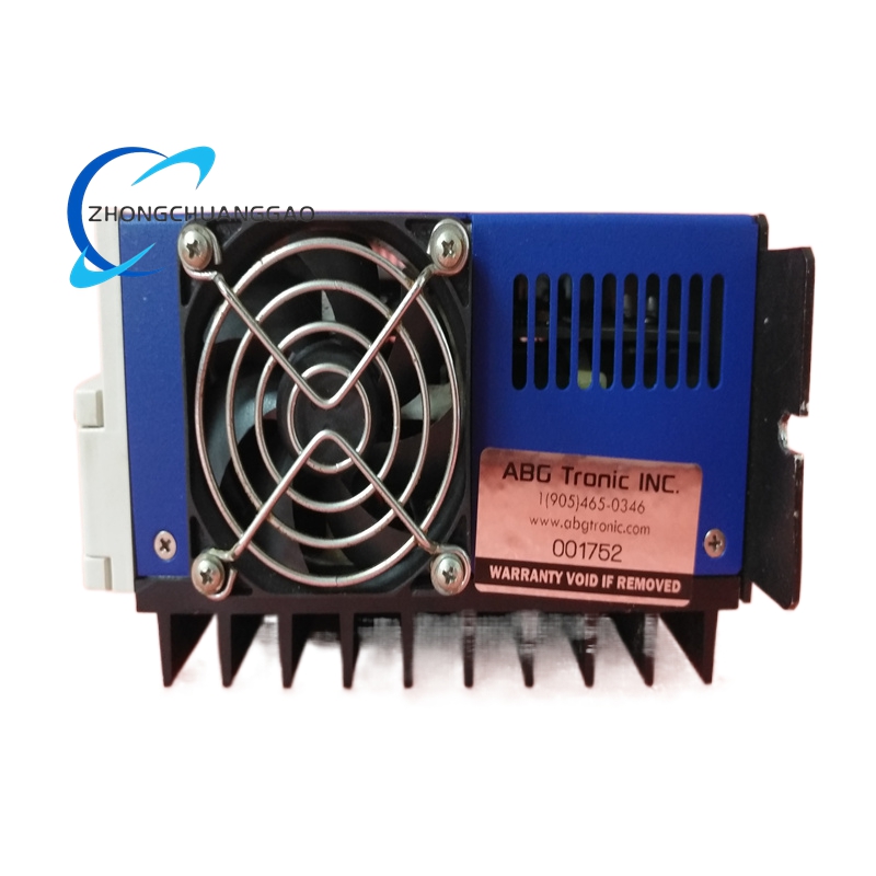
The B-604-C-A1-B2 is a fully specified variant of the B-604 braking resistor with two configuration modifiers: “A1” denotes a specific mounting/mechanical option (e.g., particular bracket or flange style), and “B2” denotes a specific electrical connection option (e.g., different terminal block or lead style). This is a custom-ordered part number for OEMs requiring a non-standard mechanical or electrical interface while retaining the core B-604 electrical performance.
Key Specifications:
| Parameter | Value |
|---|---|
| Resistance Value | 4 Ω (±5%) |
| Rated Continuous Power | 600 W |
| Peak Power (10 sec) | 1200 W |
| Max DC Bus Voltage | 565 VDC |
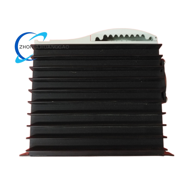
| Enclosure | Extruded Aluminum, Anodized |
| Cooling | Natural Convection |
| Mounting Option | A1 — Specific flange/bracket configuration |
| Terminal Option | B2 — Specific terminal/lead configuration |
| Operating Temperature | -20°C to +80°C |
| IP Rating | IP20 |
| Weight | Approximately 1.5 kg |
Structural Features:
Working Principle:
Identical to all B-604 series resistors. Regenerative energy from motor deceleration is routed through the resistor by the servo drive’s braking transistor, converting kinetic energy to thermal energy dissipated via the aluminum housing.
Advantages:
Applicable Industries:
Same as B-604 series — any application requiring dynamic braking with custom mounting/wiring.
Installation Requirements:
Usage Precautions: