

Digital guide
You are here:
- Home
- Kollmorgen
- Kollmorgen B-202-C-11-B3
Kollmorgen B-202-C-11-B3
Product Introduction
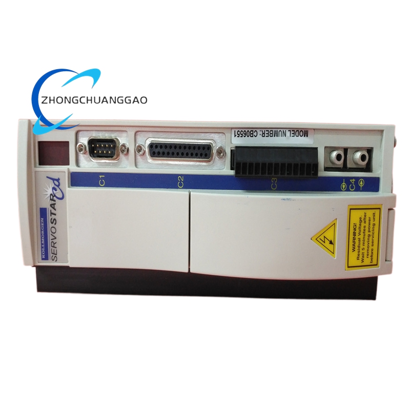
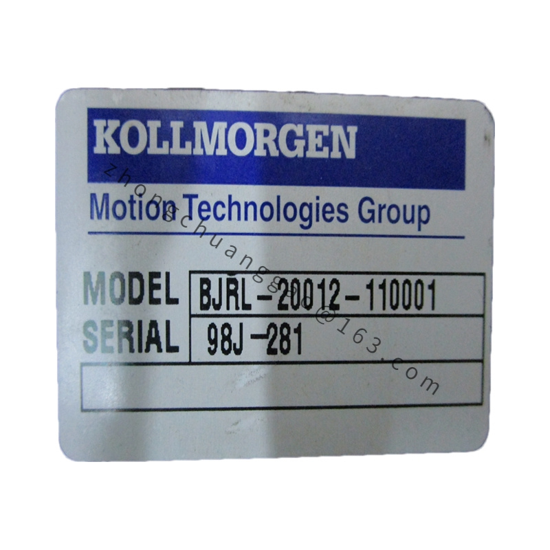
Classic analog closed-loop servo amplifier of Kollmorgen B series, model code decomposition: B series analog drive platform, 202 power tier, C standard control logic, 11 factory fixed analog parameter curve preset, B3 single resolver feedback interface hardware variant. Designed for legacy analog motion control equipment renovation replacement, compatible analog ±10V velocity/torque command industrial control systems without digital bus communication function.
Detailed content
Technical Specifications & Core Performance Parameters (Bold Key Data)
- Input Power Supply: Single-Phase AC 110V / 230V switchable, 50/60Hz
- Rated Continuous Output Current: 2.0 Arms
- Peak Transient Output Current: 6.0 Arms (2-second maximum sustain)
- Maximum Matching Servo Motor Power: 0.75kW continuous rated power
- Control Loop Architecture: Analog hardware closed-loop (current loop analog op-amp circuit, velocity loop analog PI regulator, position loop external analog command input)
- Feedback Interface Hardware (B3 Variant Exclusive): Single-channel resolver signal input only, no digital encoder interface support
- Analog Command Input: ±10VDC velocity/torque reference signal, 0~10VDC unipolar position command
- Adjustable Analog Parameters (Factory Preset Code 11): Fixed PI gain bandwidth, fixed acceleration ramp curve, no user programmable digital parameter storage
- Physical Dimension: W 65mm × H 220mm × D 165mm
- Net Weight: 1.7kg
- Protection Class: IP20 cabinet internal installation only
- Operating Ambient Temperature: 0°C ~ +40°C full rated output; derate 3%/°C above 40°C
- Storage Temperature Range: -20°C ~ +55°C
- Humidity Limit: ≤85% RH, non-condensing operating environment
- Certifications: UL, cUL, CE analog industrial control equipment safety certification
Material Composition
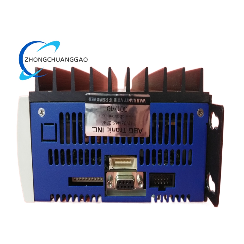
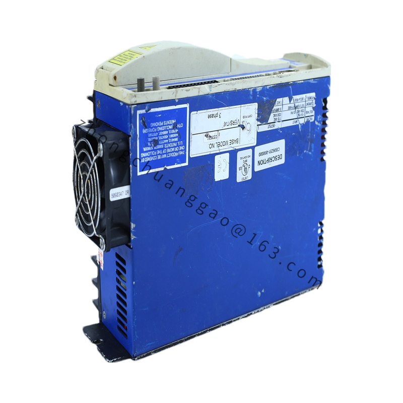
- Outer Housing: Thin cold-rolled steel black matte anti-static coating
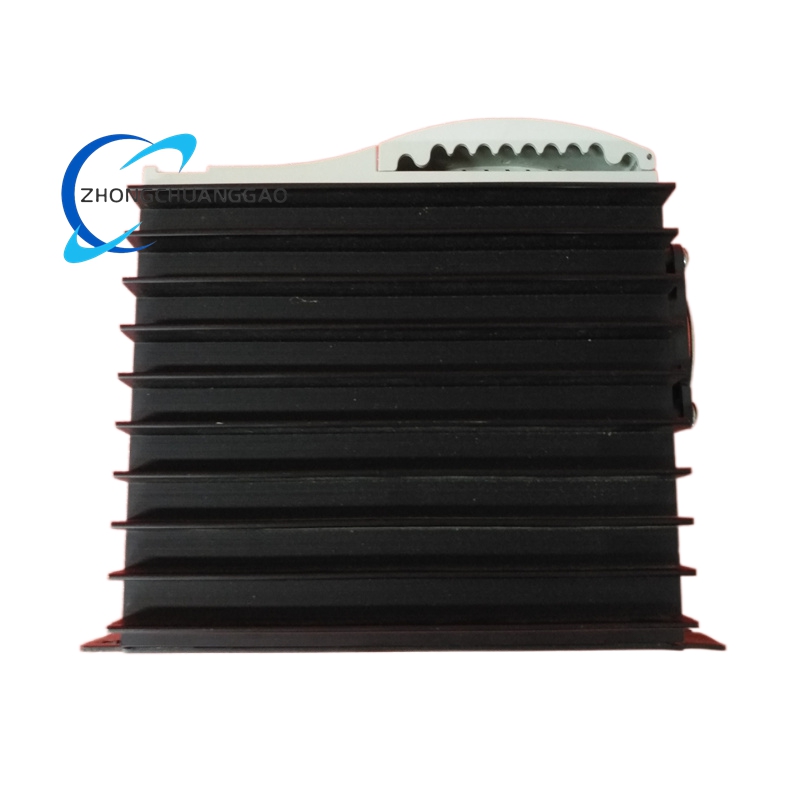
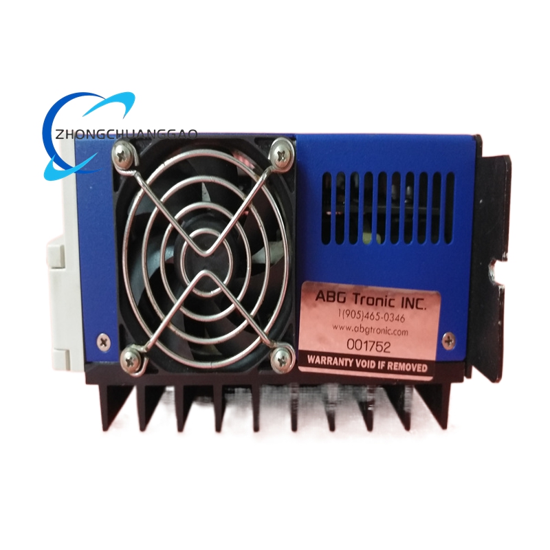
- Heat Dissipation Module: Passive extruded aluminum alloy fin heat sink without built-in cooling fan
- Analog Control Circuit Board: FR-4 fiberglass PCB with high-precision operational amplifiers, metal film fixed resistors, polypropylene film capacitors
- Power Stage Circuit: Silicon bipolar power transistor three-phase power bridge analog modulation
- Terminal Blocks: Nickel-plated copper signal and power terminals, flame retardant PA66 plastic insulation housing
- Internal Suppression Components: Ferrite ring EMC inductors, varistor overvoltage protection devices
Structural Features
- Narrow-body vertical DIN rail mounting design compatible with standard 35mm industrial cabinet rails
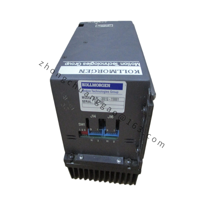
- Front panel split terminal layout: Upper analog signal terminals, lower motor power input/output terminals
- Front panel multi-turn analog potentiometer adjustment knobs for user fine-tuning of PI gain and acceleration ramp parameters
- Three analog status indicator lamps: Power On, Overcurrent Fault, Axis Running State
- B3 hardware variant single resolver feedback terminal block, no reserved digital encoder expansion interface space
- Full analog hardware circuit architecture without digital DSP processor or flash memory storage chip
Working Principle
- Single-phase AC mains input converted to DC power supply via analog rectifier circuit for power stage and analog control op-amp circuit
- External analog ±10V command signal input to velocity/torque analog PI regulator hardware circuit
- Resolver feedback signal converts rotor mechanical position to analog voltage feedback signal, compare with command voltage to generate analog error adjustment signal
- Analog error signal drives three-phase power transistor analog sine-wave modulation circuit to output adjustable amplitude alternating current to servo motor stator windings
- Hardware analog overcurrent, overvoltage and over-temperature protection circuit instant cuts power stage drive signal upon parameter threshold exceedance, no digital fault code storage function
Function Characteristics
- Full analog hardware closed-loop control architecture, no digital communication bus, compatible with legacy analog motion control PLC and motion controllers
- Factory preset analog parameter curve code 11 optimized for low-inertia small AKM series servo motors
- Multi-turn front panel potentiometers allow user manual fine adjustment of proportional gain, integral gain and acceleration/deceleration ramp slope
- Single resolver feedback interface exclusive to B3 variant, no digital absolute/incremental encoder signal decoding capability
- Hardware analog current limiting protection without software parameter configuration, fixed overload threshold non-adjustable
- No internal motion program storage function, all motion trajectory commands rely on external analog host controller output signal
Advantage Highlights
- Direct drop-in replacement spare part for legacy Kollmorgen analog servo equipment renovation, zero mechanical cabinet modification required
- Pure analog circuit zero digital processing delay, ultra-fast analog closed-loop response for high-speed analog command follow-up equipment
- Passive heat sink structure without cooling fan, eliminate fan dust failure risk for long-term unattended equipment operation
- Simple analog parameter adjustment via front panel potentiometers, no dedicated PC configuration software required for commissioning
- Compact narrow body size occupies minimal cabinet space for small analog automated machinery renovation projects
- Low electromagnetic interference analog modulation circuit compatible with old analog sensor signal acquisition systems
Applicable Industries
Legacy analog CNC machine tool renovation projects, old printing label analog slitting equipment, vintage textile analog warp knitting machinery, small analog automated assembly equipment, laboratory analog precision positioning test platforms
Installation Requirements
- Vertical mounting on standard 35mm DIN rail; maintain 70mm minimum top/bottom ventilation clearance for passive heat sink convection cooling
- Servo motor power cable cross-section ≥1.0mm² copper wire; resolver feedback cable must use dedicated shielded twisted pair analog signal cable
- Unified cabinet grounding bar connection, grounding resistance ≤4Ω; signal cable shield layer single-end grounded at drive terminal side only
- Analog command signal wiring and motor power wiring laid in independent cable troughs, minimum 10cm separation distance to eliminate analog voltage signal interference
- Installation environment free of metal dust, oil mist and condensation; air filter installed at cabinet air intake for dusty workshop renovation sites
Usage Precautions
- Cut off main AC power supply and wait 5 minutes for DC bus capacitor discharge before adjusting front panel analog potentiometers or disassembling wiring terminals
- Forbid motor three-phase output terminal short-circuit under powered state; analog power transistor bridge suffers permanent breakdown damage
- Analog command signal wire cannot share wiring trough with high-frequency inverter power cables; coupling interference causes severe motor velocity jitter
- Avoid continuous operation above 40°C ambient temperature; passive heat sink over-temperature triggers unadjustable hardware current limiting and torque reduction
- Do not install near high-vibration stamping or cutting equipment; long-term vibration loosens analog potentiometer internal sliding contacts and generates unstable velocity signals
- Conduct quarterly visual inspection of heat sink fins for dust accumulation; accumulated dust blocks natural airflow and accelerates component aging
- No digital fault storage function; all fault judgment relies on front panel indicator lamp status, record lamp state immediately after equipment fault shutdown for troubleshooting

.jpg)
.jpg)