Brake Type: Fail-safe, spring-applied, electromagnetically released
Rated Voltage (Release): 24 V DC ± 10 %
Rated Power Consumption (Hold/Release): ≈ 12 – 18 W (typical for SEB-204 size)
Holding Torque (Static): ≈ 1.8 – 2.5 Nm (SEB-204 typical — matches motor continuous stall torque class; verify exact value on brake nameplate — common is 2.0 Nm or 2.5 Nm)
Maximum Release Time (Typical): < 50 ms after voltage applied
Engagement Time (Fall-off): < 30 ms after voltage removed (friction engagement)
Duty Cycle: 100 % ED (continuous energized when released; brake only dissipates holding coil power when released — no heating in engaged state)
Friction Lining: Organic / sintered (non-asbestos) — wear-compensated design
Operating Temperature: –20 °C to +60 °C (ambient at motor non-drive end)
B10d Life (Typical): > 1,000,000 cycles (light load); > 15,000,000 cycles per some Kollmorgen docs for brake-only
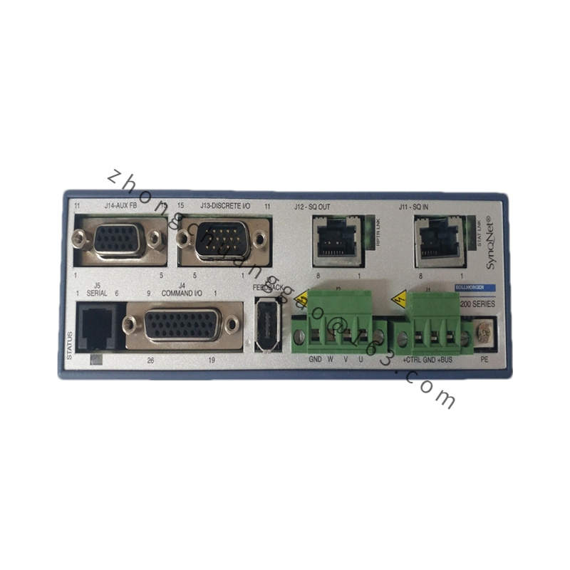
Mounting: Bolted to motor rear flange; couples to motor shaft via keyed or spline adapter (integral to brake hub)
Connector: Typically 2-wire flying leads or mating connector (same as motor brake circuit)
Weight: ≈ 0.4 – 0.6 kg
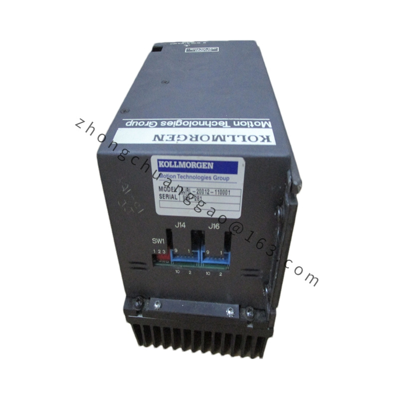
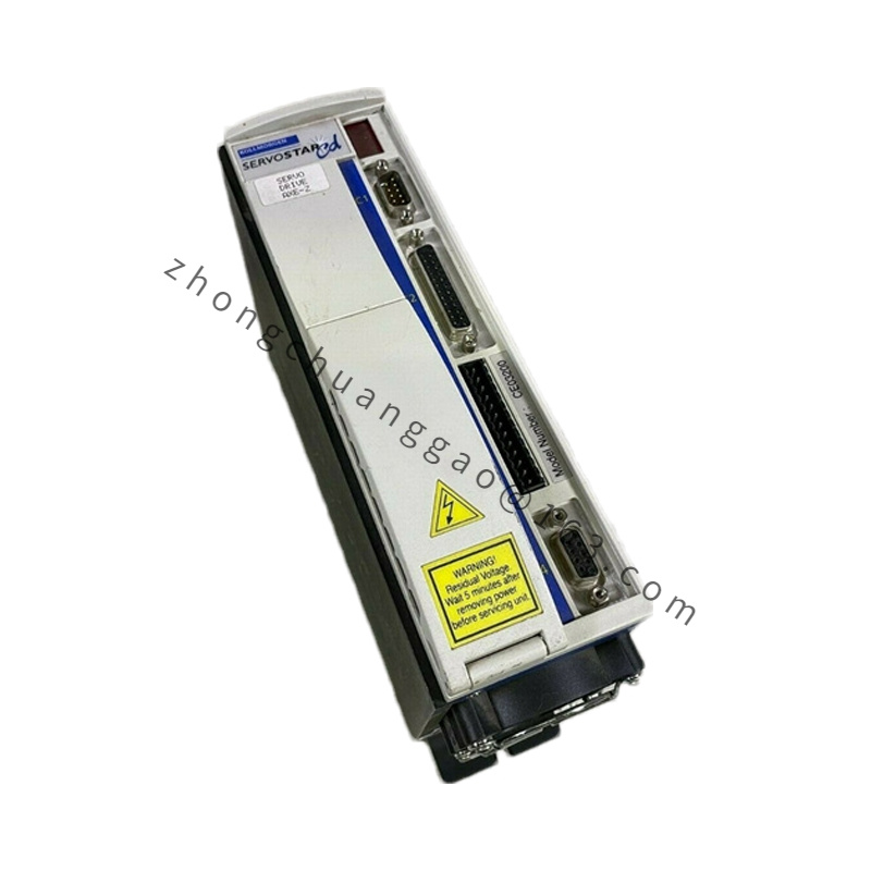
Compatibility: Goldline B-20x series (B-204/B-206) with brake provision; also some AKM62/63 with SEB-204 adapter kits
Applicable Industries: Any vertical axis or load-hold application using Goldline B-series — packaging formers (vertical fill), hoist/raise axes, medical imaging gantry locks, textile creel positioners
Installation Requirements: Brake must be factory-installed or retrofitted with proper shaft coupling; 24 VDC supply must be capable of inrush (typically 2× holding current briefly); wire brake + / – per motor cable brake pair; drive or external brake control relay should delay brake release until motor is enabled / speed ≈ 0 on stop.
Usage Notes: Brake is not a stopping (dynamic) brake — do NOT use to decelerate load from running speed; always bring motor to low speed/stop via electronic braking before allowing brake to engage; check brake release voltage at brake terminals under load — voltage drop > 10 % may prevent full release; periodical visual inspection of brake gap (wear indicator) recommended per maintenance schedule.


.jpg)