.jpg "S61000(3)")

Digital guide
You are here:
- Home
- Kollmorgen
- Kollmorgen S72402-NANANA
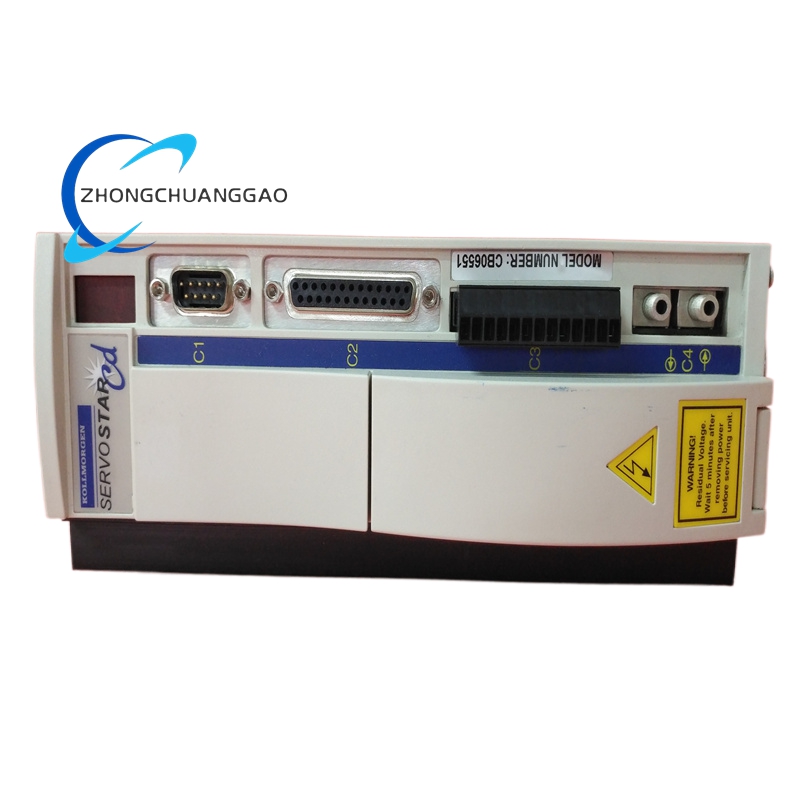
Kollmorgen S72402-NANANA
Product Overview
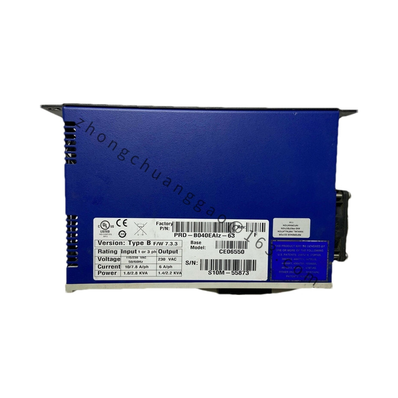
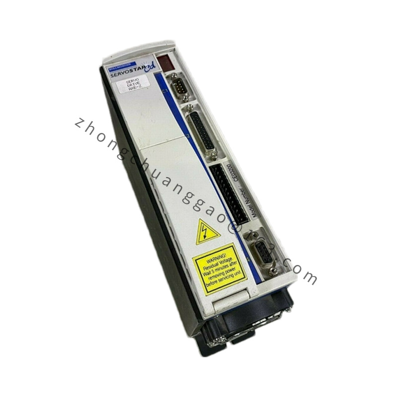
S72402-NANANA is medium-current digital servo drive under Kollmorgen DIGIFAS S7200 platform. Model decoding: S72 = S7200 generation wide-input drive series identifier; 4 = 4 Arms continuous three-phase output current grade; 02 = 80–480V ultra-wide single/three-phase mains input hardware base variant; suffix NANANA = full base factory standard configuration without optional STO safety modules, external braking chopper daughter boards or proprietary fieldbus expansion cards, equipped with native CANopen, RS232 and analog ±10V command input interfaces only.
Detailed content
Technical & Performance Specifications
- Mains Input Voltage Range: Single/Three Phase 80–480 VAC (±10%), 50/60Hz ultra-wide industrial grid tolerance
- Continuous Per-Phase Output Current: 4 Arms RMS
- Peak Overload Output Current: 11.2 Arms RMS, sustainable maximum 5 seconds (280% continuous overload capacity)
- Nominal DC Bus Intermediate Circuit Voltage: 560 VDC standard operating voltage
- Supported Closed-Loop Control Modes: Torque closed-loop, velocity closed-loop, position closed-loop
- Static Angular Position Control Accuracy: ±0.001° rotor angular positioning resolution
- Maximum Supported Motor Operating Speed: 6000 RPM
- Auxiliary Independent Control Power Supply Requirement: 24VDC auxiliary logic power, operating tolerance range 18–36VDC
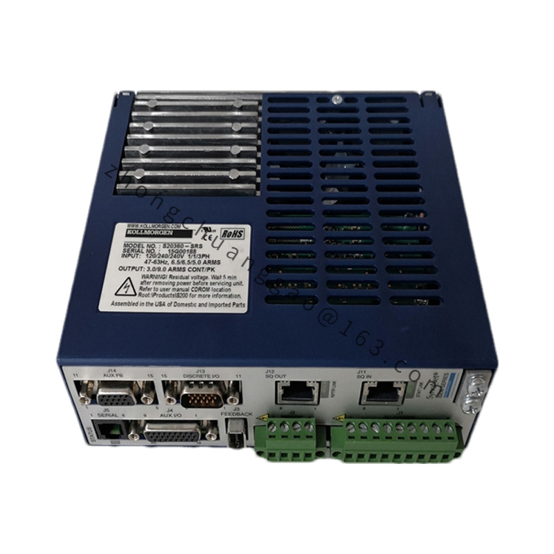
- Standard Onboard Communication Interfaces: RS232 diagnostic configuration port, CANopen DS402 industrial motion bus
- Native Feedback Hardware Compatibility: Multi-pole resolvers, SFD smart single-cable feedback devices, EnDat 2.2 serial absolute encoders, BiSS serial encoders
- Digital I/O Channels: 6 × 24VDC optical isolated sinking/sourcing input channels, 4 × 24VDC isolated open-collector output channels
- Full Protection Mechanism Suite: Overcurrent instantaneous shutdown, DC bus overvoltage/undervoltage lockout, heatsink thermal cut-off protection, encoder/resolver feedback loss interlock, output phase short circuit protection, earth leakage fault interlock
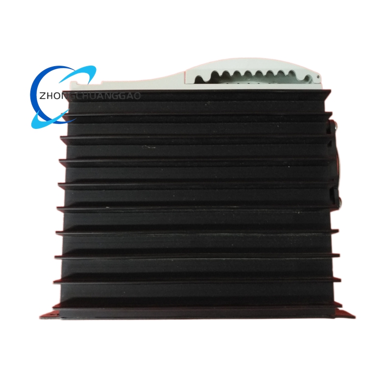
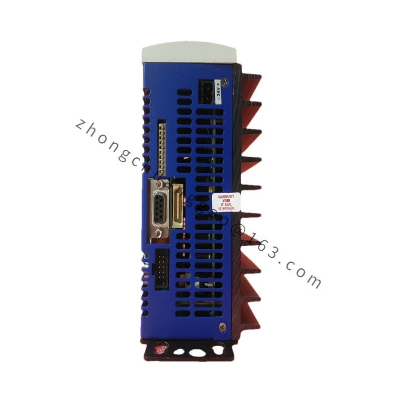
- Cooling Architecture: Passive cast aluminum alloy fin heat sink natural convection fanless cooling design
- Protection Class: IP20, installation restricted to inside industrial control cabinets only
- Net Unit Weight: 2.4 kg
- Outer Physical Dimensions (W × H × D): 85 mm × 320 mm × 200 mm
Material Composition
- Main Chassis Frame: Galvanized cold-rolled steel sheet anti-rust base frame with matte black electrostatic anti-static paint coating
- Heat Dissipation Radiator: Cast high-density aluminum alloy finned heat sink thermally bonded to power IGBT semiconductor module
- Main Control Circuit PCB: Double-layer FR4 flame-retardant printed circuit board with gold-plated low-signal contact pins
- Power Terminal Blocks: High-temperature PA66 insulated nickel-plated copper screw terminal connectors
- Feedback Signal Connectors: Shielded 15-pin D-Sub industrial connectors with silicone EMI sealing gaskets
- Internal Power Wiring: High-temperature silicone insulated stranded copper wire with braided shielding layer
Structural Features
- Compact horizontal cabinet form factor engineered for narrow-width multi-axis heavy industrial control enclosure layouts
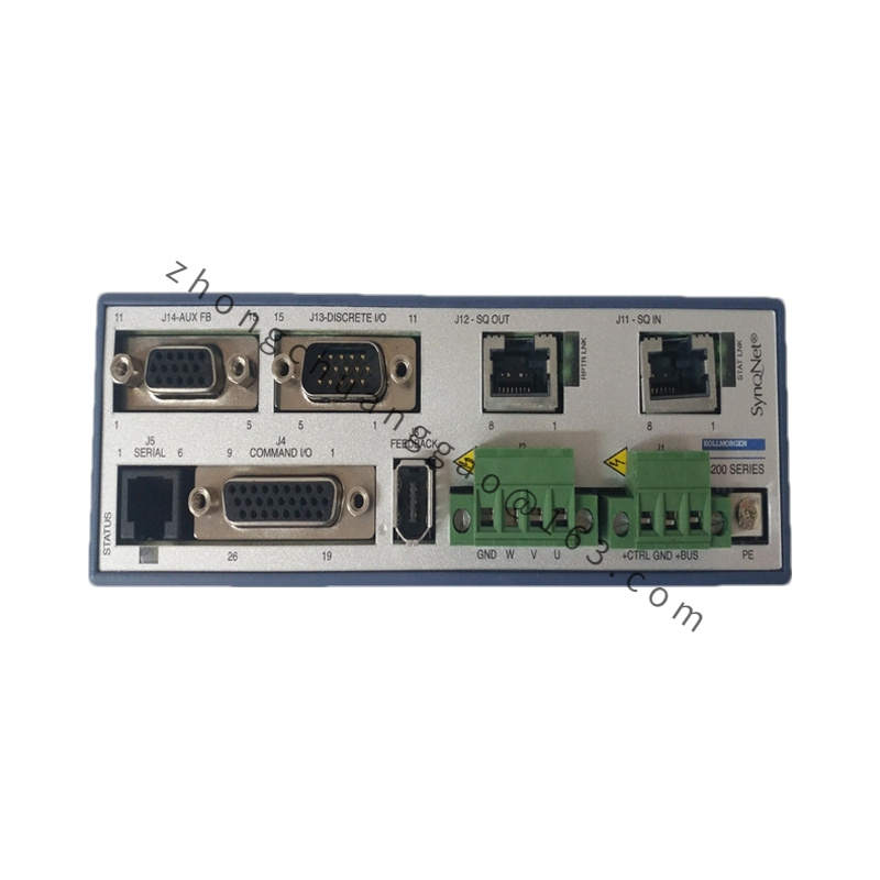
- Front panel terminal layout physically segmented into independent high-voltage power zone and low-voltage signal/communication zone separated by metal EMI isolation barrier
- External empty expansion slot reserved for optional aftermarket braking chopper and proprietary fieldbus communication daughter boards (not pre-installed on NANANA base variant)
- Dedicated fully independent terminal block for auxiliary 24VDC control logic power supply, electrically isolated from main three-phase mains input circuit
- Separated dedicated resolver/encoder feedback wiring compartment with integrated internal signal metal shielding to suppress feedback signal electromagnetic noise
- Onboard non-volatile flash memory permanently stores all configured motor parameters and motion trajectory profiles through complete power cycle interruptions
Working Principle
Ultra-wide range single/three-phase AC mains input passes built-in passive EMC filtering circuit, then full-wave diode rectifier to generate stable DC bus voltage supplying three-phase IGBT power inverter stage. External analog ±10VDC torque/velocity/position reference command signals transmitted from host PLC motion controller are digitized via high-precision internal ADC converter before processing by dedicated motion DSP chip. DSP hardware executes full triple closed-loop regulation algorithms utilizing real-time resolver or serial absolute encoder rotor position feedback signals, continuously adjusting three-phase output current magnitude and phase angle to maintain target motion setpoint values without tracking deviation. Passive cast aluminum fin heat sink dissipates power semiconductor switching loss heat without forced air ventilation cooling hardware; dedicated hardware fault monitoring circuit continuously samples all critical electrical and thermal operating parameters, triggering immediate safe power stage cut-off operation once fault threshold violation is detected to protect drive and paired servo motor hardware.
Function Features
- Complete automatic system motor identification tuning function with guided graphical parameter setup workflow reducing field commissioning labor time
- Multi-protocol serial communication support enabling synchronized multi-axis coordinated motion control between multiple cascaded S7200 series drive units
- Full native compatibility with industry standard analog ±10VDC motion command signals from all mainstream PLC and motion controller hardware platforms
- Ultra-wide 80–480V mains input voltage tolerance withstands severe metal workshop factory power grid voltage fluctuation without degradation of motion control performance
- Integrated full resolver feedback signal conditioning circuit eliminating requirement for external signal amplification hardware in resolver-motor matching systems
- All user-configured motion parameters and axis tuning gain values retained in non-volatile flash memory through full mains power disconnection and power cycle operations
Advantage Highlights
- Fanless passive natural convection cooling design removes mechanical fan wear, dust clogging and fan motor burnout failure points, reducing long-term heavy industrial equipment maintenance frequency
- Ultra-wide single/three-phase universal mains input range eliminates requirement for external step-up/step-down isolation transformers for global heavy factory deployment
- High static angular positioning precision delivers superior stationary holding torque stability for low-speed continuous stationary load retention metal processing industrial applications
- Compact narrow-width horizontal chassis minimizes total cabinet space occupation for dense multi-axis heavy automation control layouts
- Robust galvanized steel chassis construction provides enhanced corrosion resistance for lightly corrosive metal workshop atmosphere operating environments
Applicable Industries
Metal stamping press auxiliary feed axes, continuous textile fiber production machinery, heavy-duty food processing automated conveyor equipment, paper slitting and winding converting machinery, light-duty metal cutting small CNC machine tools
Installation Requirements
- Mandatory vertical cabinet mounting orientation; horizontal flat mounting reduces passive heat dissipation efficiency by 40% and causes gradual power module thermal degradation
- Minimum surrounding cabinet unobstructed airflow clearance: 70 mm vertical clearance above top surface of aluminum heat sink, 50 mm lateral side clearance on left and right chassis walls
- Drive mounting metal base plate must establish secure connection to facility star protective earth grid via minimum 6 mm² solid copper earth conductor
- Physical separation rule for wiring: High-voltage power wiring and low-level signal/feedback wiring maintain minimum 15 cm separation distance; unavoidable cross routing must adopt strict 90-degree perpendicular crossing only
- Resolver/encoder feedback shielded cable maximum allowable transmission distance limited to 80 meters
Operation & Maintenance Precautions
- Cabinet ambient operating temperature range restricted strictly to 0°C ~ +40°C; ambient temperature exceeding 40°C requires linear 10% continuous output current derate per 10°C temperature rise
- Quarterly maintenance task: Use clean compressed dry air to fully remove accumulated dust buildup from aluminum heat sink fin array to maintain unobstructed passive heat dissipation airflow
- Auxiliary 24VDC control logic power supply must maintain tightly regulated output voltage within 18–36VDC tolerance range; voltage deviation outside this band triggers communication signal dropout and position feedback error
- Disconnect all three-phase mains AC supply and wait minimum 8 minutes for DC bus capacitor full discharge before accessing internal drive wiring terminals for maintenance or modification
- Strictly prohibit drive installation inside control enclosures containing heavy oil mist, conductive carbon metal dust or acidic/alkaline corrosive vapor atmospheres
- All firmware modification, motor parameter tuning and motion profile backup operations must exclusively execute via official Kollmorgen DIGIFAS dedicated configuration software; unapproved third-party configuration software voids all factory product warranty coverage