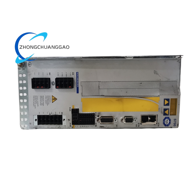
.jpg "AKD-P00606-NBA(1)")
Digital guide
You are here:
- Home
- Kollmorgen
- Kollmorgen S71201-NA
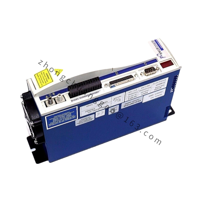
Kollmorgen S71201-NA
Product Introduction
Full-digital high-performance single-axis servo amplifier developed by Kollmorgen for medium-power precision motion control. Optimized for synchronous servo motors, linear motors and asynchronous motors, integrated multi-bus communication and SIL3 safety torque off function, standardized DIN rail cabinet mounting design for automated production lines.
Detailed content
Technical Specifications & Core Performance Parameters (Bold Key Data)
- Input Power Rating: AC 115V / 230V, 50/60Hz Single/Three-Phase
- Rated Continuous Output Current: 5.0 Arms
- Peak Output Current: 15.0 Arms (2-second maximum sustain)
- Nominal Output Power: 2.5kW / 3.3kW / 4.4kW multi-power tier matching
- DC Bus Operating Range: 160VDC ~ 455VDC; Overvoltage fault threshold 455VDC, Undervoltage fault threshold 100VDC
- PWM Switching Frequency: 8kHz fixed output stage frequency
- Control Loop Refresh Cycles:
Current Loop: 62.5μs, Speed Loop: 62.5μs, Position Loop: 250μs (125μs optional high-speed mode)
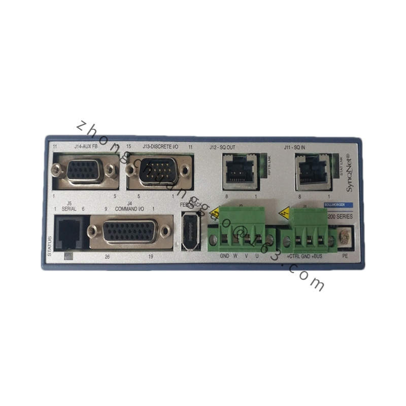
- Supported Feedback Signals: Resolver, EnDat 2.1/2.2, BiSS-C, HIPERFACE, SFD3 single-cable feedback, incremental encoder, SSI absolute encoder
- Communication Interfaces (Onboard, No Expansion Card Required): EtherCAT, CANopen, DeviceNet, PROFIBUS, SERCOS 2, analog ±10V command, pulse/direction input
- Safety Certification Grade: SIL3 / PLe (EN 61508, EN 60204-1); Dual-channel STO safety torque shutoff circuit
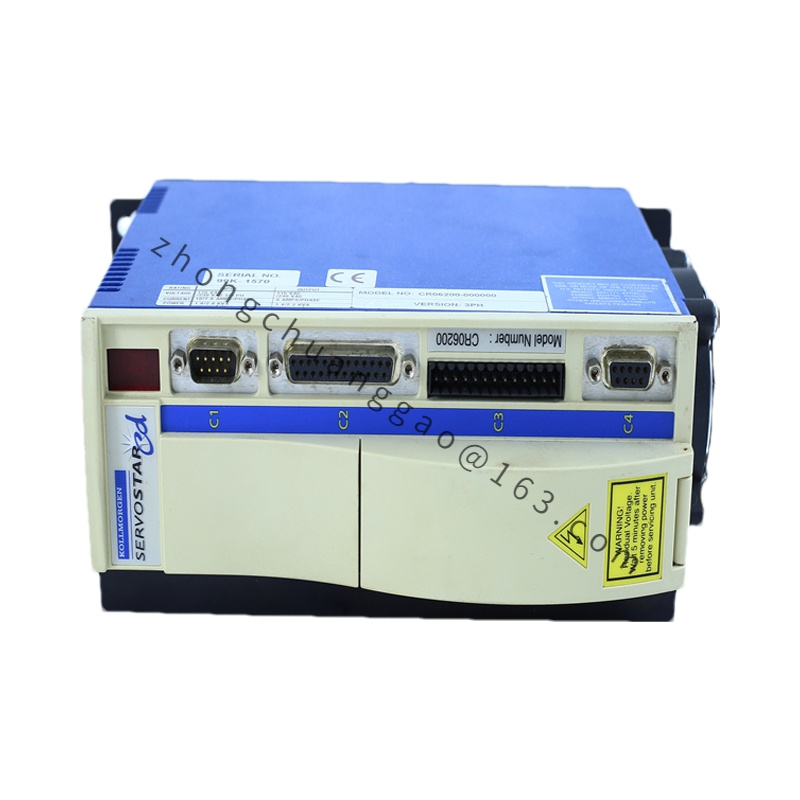
- Physical Dimension: W 70mm × H 345mm × D 243mm (excluding external connectors)
- Net Weight: 4.4kg
- Protection Class: IP20 (cabinet internal installation only)
- Operating Ambient Temperature: 0°C ~ +40°C full rated output; 40°C ~ 55°C linear derate 2.5% per °C
- Storage Temperature Range: -25°C ~ +55°C
- Allowable Relative Humidity: ≤85%, zero condensation permitted
- Max Operating Altitude: 1000m without power derating; 6% power reduction per additional 1000m elevation
Material Composition
- Outer Housing: Cold-rolled steel plate with black matte anti-corrosion electrophoretic coating
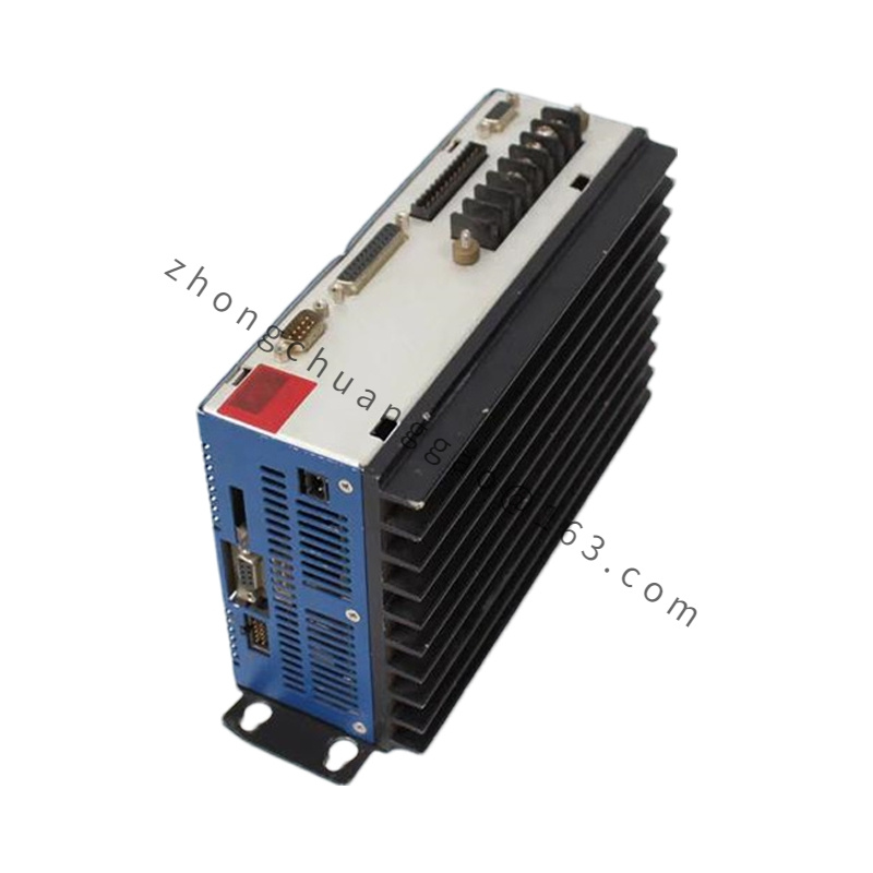
- Power Heat Sink: Extruded high-purity aluminum alloy with finned forced air cooling structure
- Main Control PCB: FR-4 high-temperature resistant fiberglass substrate, tin-lead free industrial grade solder
- Power IGBT Module: Silicon insulated gate bipolar transistor with built-in temperature thermistor
- Terminal Connectors: Copper alloy terminals with nickel plating, flame-retardant PA66 plastic insulation housing
- Internal Filter Components: Metal film EMC suppression capacitors, ferrite ring magnetic core inductors
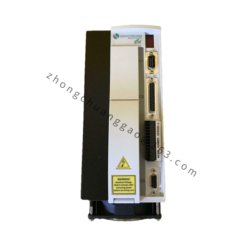
Structural Features
- Vertical DIN rail mounting structure, standard 35mm cabinet rail compatible
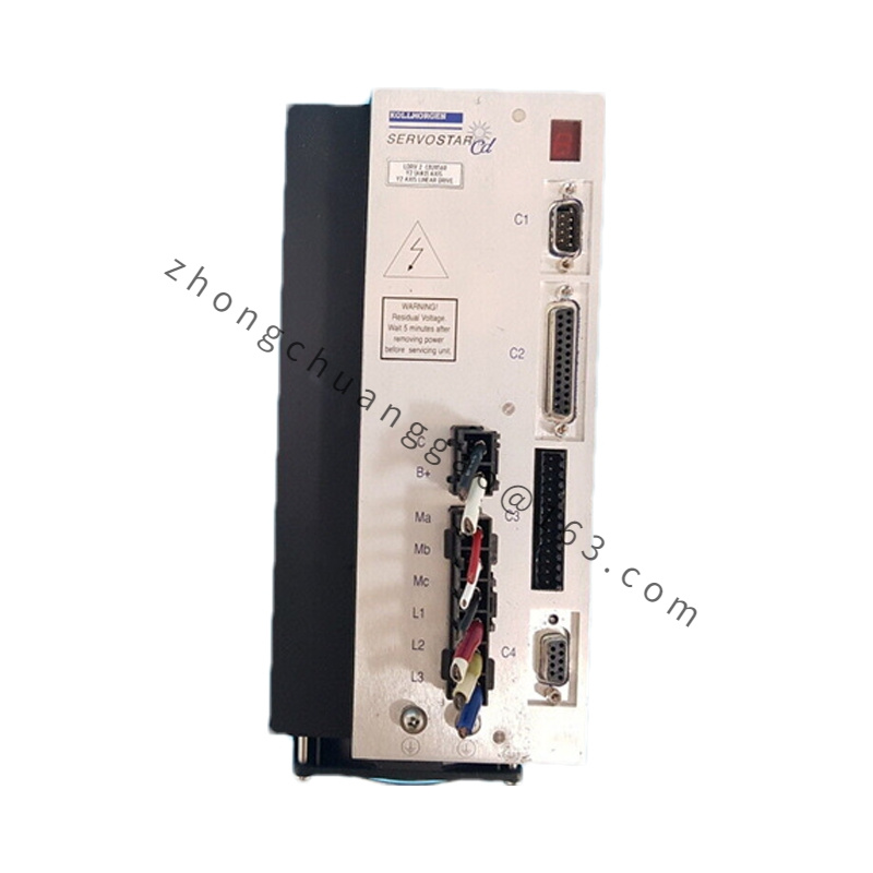
- Separate upper signal connector zone and lower high-power terminal zone, physical isolation of strong/weak current circuits
- Built-in integrated EMC power filter and regenerative braking resistor module, no external accessory required for basic braking function
- Front panel status LED array: Power, Fault, Bus Communication, STO Safety, Axis Running indicator lights
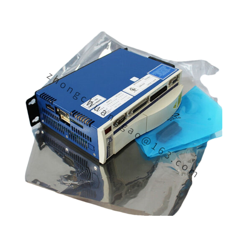
- SD card slot on front panel for offline parameter storage, firmware batch upgrade without host computer
- Internal layered shielding metal partitions to eliminate cross-interference between power circuit and control circuit
Working Principle
- AC mains input passes built-in rectifier to convert alternating current to stable DC bus voltage; IGBT power bridge executes sine-wave vector PWM modulation to output three-phase adjustable frequency/voltage power to servo motor stator windings
- Real-time collection of motor rotor position via feedback encoder; triple closed-loop algorithm (current-speed-position) operates in synchronous cycle to dynamically adjust output current amplitude and phase
- Onboard 32-bit floating-point DSP processor executes motion control logic, electronic cam, electronic gear, flying shear and positioning program via built-in IEC 61131 macro programming language
- Dual-channel STO hardware circuit directly cuts power drive gate signal upon safety trigger, mechanical contactor independent of control software to achieve zero torque output within 2μs
- Real-time monitoring of DC bus voltage, output current, heat sink temperature and motor winding temperature; automatic trigger of hardware protection cutoff when parameter exceeds rated threshold
Function Characteristics
- Multi-mode control support: Torque mode, velocity mode, absolute/relative position mode, homing positioning, multi-segment motion profile continuous execution
- Automatic motor parameter identification: One-click self-tuning of winding inductance, rotor inertia, cogging torque compensation coefficient
- Built-in encoder emulation output: A/B/Z quadrature signal for secondary slave axis synchronization without additional signal conversion module
- 31-channel expandable digital I/O: 13 digital input, 4 digital output, 1 analog input, 1 analog output for external sensor and actuator linkage
- Real-time fault waveform recording: Store 10 groups of pre-failure current/velocity/position data for rapid fault diagnosis
- Multi-axis synchronous bus synchronization: EtherCAT bus minimum communication cycle 125μs, support synchronous control of 128 axes on single master station
Advantage Highlights
- Ultra-fast triple loop response bandwidth, speed loop maximum bandwidth 600Hz, ultra-low velocity ripple <2% under 10rpm low-speed operation
- Integrated all mainstream industrial bus protocols, eliminate additional communication expansion card procurement cost
- SIL3 dual-channel STO safety function integrated as standard, meets global machinery safety certification standards without external safety relay
- Single-cable SFD3 feedback compatibility, reduce field wiring quantity by 50% and lower electromagnetic interference risk
- Onboard EMC filter eliminates external filter module, compact cabinet layout reduces overall equipment volume
- SD card offline parameter backup realizes batch equipment consistent configuration, shorten production commissioning cycle by 70%
Applicable Industries
Precision CNC machine tools, semiconductor wafer handling equipment, lithium battery winding & slitting machinery, high-speed printing & labeling equipment, automated packaging production lines, 3C electronic assembly robots, medical precision positioning equipment, textile high-speed warp knitting machinery, laser cutting engraving equipment
Installation Requirements
- Mount vertically on standard 35mm DIN rail inside sealed electrical cabinet; maintain 100mm minimum top/bottom ventilation clearance, 20mm left/right clearance between adjacent drives
- Cabinet forced cooling fan mandatory when continuous operating temperature exceeds 40°C; airflow direction parallel to drive heat sink fins
- Power cable cross-section ≥2.5mm² copper wire for rated 5A output; feedback signal cable must use double-shielded twisted pair dedicated servo cable
- Equipment grounding terminal connected to cabinet unified ground bar; grounding resistance ≤4Ω, grounding wire cross-section ≥4mm²
- Strong power wiring and weak signal wiring separate wiring trough, minimum 15cm separation distance to avoid electromagnetic coupling interference
- Installation environment strictly isolated from metal dust, corrosive gas, oil mist and water vapor; air filter installed at cabinet air intake
Usage Precautions
- Power input voltage deviation must be limited within ±10% rated voltage; voltage fluctuation exceeding range triggers permanent overvoltage hardware damage
- Disconnect main power supply and wait 10 minutes for DC bus capacitor full discharge before disassembling wiring connectors to prevent electric shock hazard
- Forbid direct short-circuit of motor three-phase output terminals when drive powered on; instantaneous short-circuit causes IGBT module breakdown
- Do not operate under condensation environment; moisture infiltration leads to PCB short-circuit and insulation breakdown
- Avoid installation near vibration sources (stamping machines, vibratory screening equipment); continuous vibration loosens internal solder joints and terminal wiring
- Conduct annual full inspection of heat sink dust accumulation; dust blocking cooling fins causes over-temperature protection and drive shutdown
- STO safety circuit wiring must adopt independent dual twisted shielded cable, cannot share wiring with other digital signal lines
.jpg)