
Digital guide
You are here:
- Home
- Kollmorgen
- Kollmorgen M00306-M1E
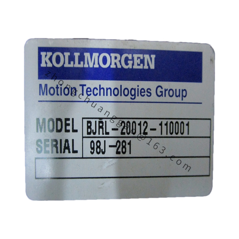
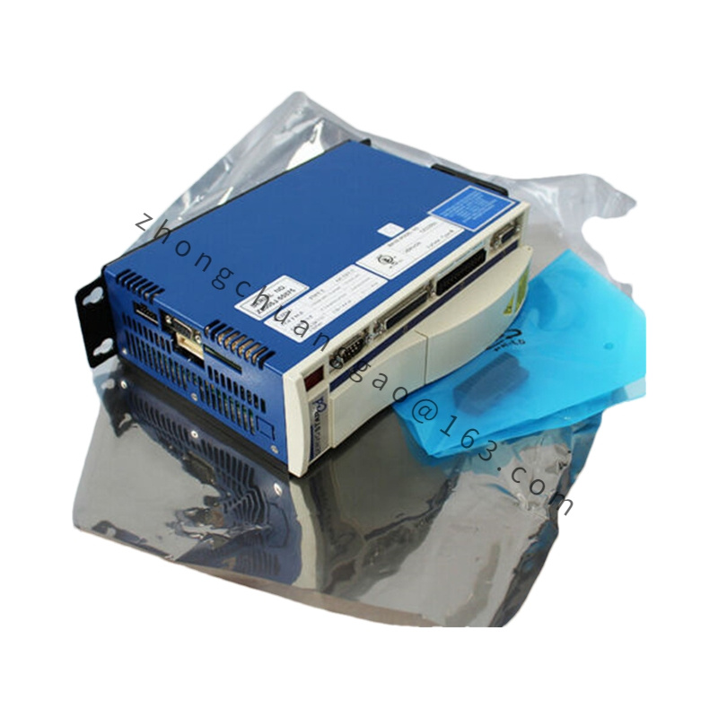
Kollmorgen M00306-M1E
Product Brief Introduction
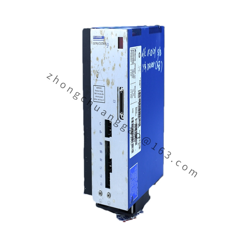
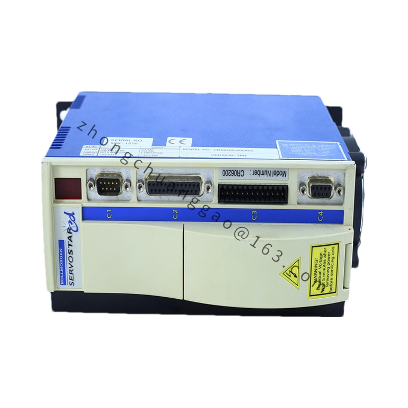
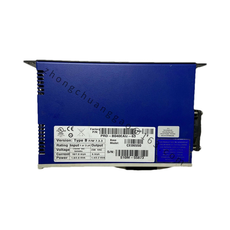
M00306-M1E is a rack-mount signal interface module developed for legacy analog motion control systems, used to convert host controller digital position commands into analog ±10V speed reference signals, while conditioning motor tachometer and encoder feedback signals for PRD series analog servo amplifiers. M1E suffix defines single-channel motor signal processing circuit, European CE safety certification, standard terminal block wiring configuration, integrated overvoltage signal protection circuit.
Detailed content
Technical Specifications
- Command Input Electrical Parameters
- Digital Command Input Voltage: 24 VDC sink/source logic signal
- Analog Speed Command Output Range: ±10 VDC differential output
- Analog Output Drive Capacity: ±10 mA maximum load current
- Command Signal Conversion Bandwidth: 400 Hz
- Feedback Signal Processing Parameters
- Tachometer Input Signal Acceptance Range: 0 ~ 30 VAC analog sine wave
- Encoder Digital Input Frequency Maximum: 250 kHz
- Feedback Input Impedance: 120 kΩ differential high impedance
- Protection Circuit Threshold Parameters
- Analog Signal Overvoltage Protection Threshold: ±12 VDC clamp limit
- Digital Input Overvoltage Protection Threshold: 30 VDC transient clamp
- On-board Thermal Over-temperature Trip Threshold: 75°C PCB surface
- Power Supply Operating Parameters
- Module Auxiliary Operating Power: 24 VDC ±10% DC input
- Rated Module Operating Current: 0.28 A
- Environmental Mechanical Specs
- Operating Ambient Temperature: 0°C ~ +50°C
- Storage Temperature: -30°C ~ +75°C
- Enclosure Protection Rating: IP20 rack cabinet indoor use only
- Standard Mounting: 3U industrial standard rack slide rail mounting
Functional Features
- Single-channel independent analog speed command conversion for one-axis brushed servo motor closed-loop control
- Dual signal processing channel supporting both analog tachometer generator and quadrature digital encoder feedback input
- Hardware analog low-pass filter built-in to suppress industrial site high-frequency EMI noise on feedback wiring
- Bidirectional ±10V differential analog output fully compatible with PRD series analog servo amplifier command port
- Dual-layer overvoltage transient protection circuit for all input/output signal terminals to resist industrial power grid surge interference
- On-board LED status indicators for power supply, command signal active, feedback signal valid and fault alarm states
- Galvanic isolation barrier between 24VDC digital control circuit and analog low-voltage signal circuit to eliminate ground loop offset error
- CE certified European standard hardware compliant with EN 61010 industrial control module safety requirements
Working Principle
24VDC auxiliary power energizes module internal logic and analog signal processing circuits. Digital position pulse commands transmitted from upper motion controller enter isolated digital input channel, converted via internal D/A conversion circuit into proportional ±10VDC differential analog speed command signal, output to PRD analog servo amplifier speed reference terminal. Motor tachometer analog voltage or quadrature encoder digital pulse feedback signal from servo motor enters dedicated conditioning circuit, filtered and amplified to standardized signal level, then transmitted back to host motion controller for closed-loop position deviation calculation. Built-in transient voltage suppression components clamp abnormal overvoltage surge signals instantly to protect internal operational amplifier and digital logic chips from permanent breakdown. On-board temperature sensor triggers fault indicator light and signal lockout once PCB temperature exceeds 75°C threshold.
Material Composition
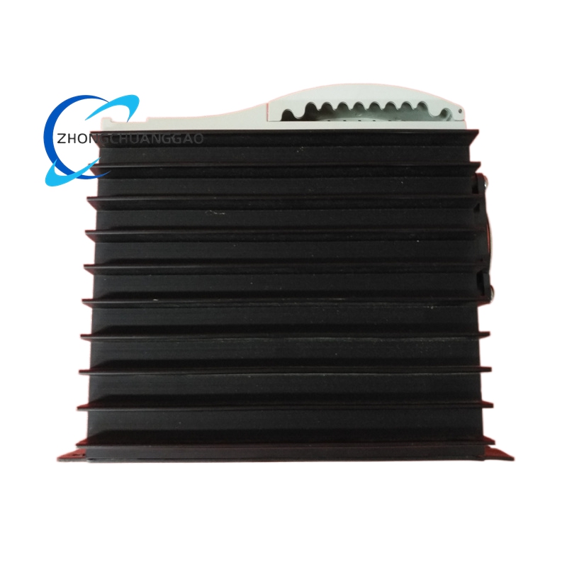
- Module Front Panel: Black anodized 6063 aluminum alloy 3U rack panel
- Circuit Substrate: FR4 high-temperature flame retardant double-sided PCB with lead-free solder process
- Analog Core Components: Precision low-drift operational amplifiers, metal film trimming resistors, polypropylene signal capacitors
- Digital Logic Components: CMOS isolation optocouplers, high-speed pulse counting logic chips
- Terminal Hardware: Nickel-plated copper screw terminal blocks with UL94-V0 PA66 flame retardant plastic housings
- Protection Components: TVS transient voltage suppression diodes, positive temperature coefficient resettable fuses
- Mounting Hardware: Zinc-plated carbon steel rack slide rails and fixing screws
Structural Characteristics
- Standard 3U industrial rack module dimension: 128mm width × 133mm height × 160mm depth
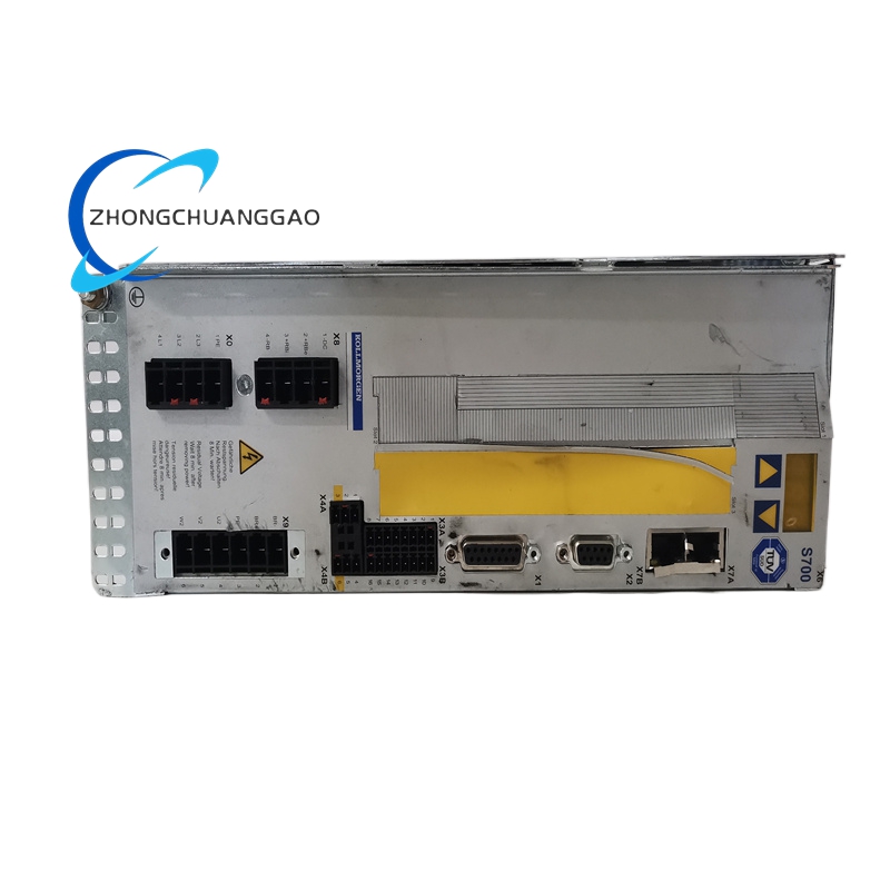
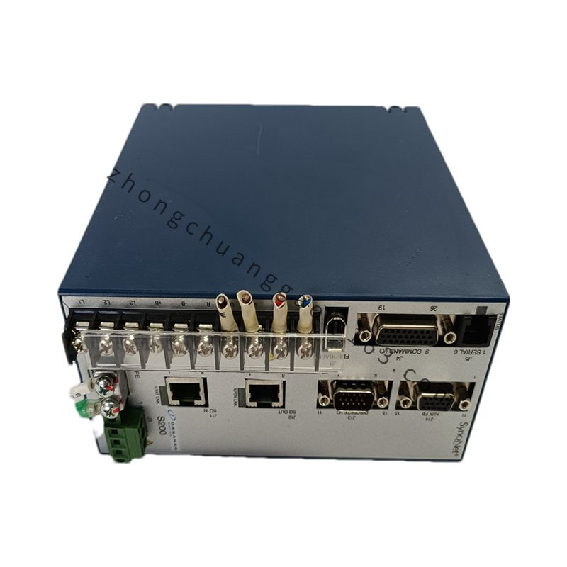
- Front panel divided functional zones: power status LED, fault indicator LED, digital input terminal block, analog output terminal block, feedback input terminal block
- Internal PCB layered zoning: isolated digital signal zone, analog signal conditioning zone, power supply circuit zone to reduce signal crosstalk
- Rear rack slide rail locking structure for quick plug-and-play replacement without full rack power cut-off
- All signal terminals adopt screw locking design to prevent loose wiring caused by cabinet vibration
- Internal independent metal shielding partition separating analog and digital circuit regions
Advantage Highlights
- Perfect signal matching bridge for legacy B series brushed servo and PRD analog amplifier system, no extra signal conversion adapter required
- Dual feedback input compatibility supports both tachometer and encoder retrofitting upgrade of old analog machine tools
- Galvanic isolation design completely eliminates ground loop signal drift in multi-axis mixed analog-digital control cabinets
- Built-in multi-stage surge protection improves system stability under factory unstable power grid conditions
- Visible front panel LED status lights allow fast on-site fault diagnosis without external measuring instruments
- Standard 3U rack form factor compatible with mainstream European industrial control rack cabinets
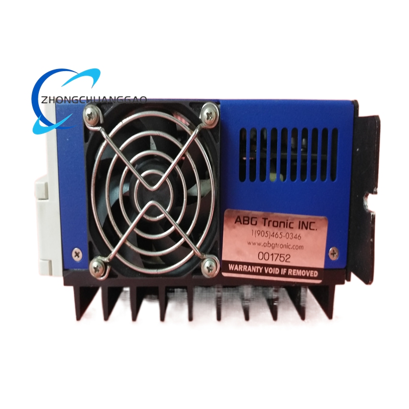
- Low power consumption design reduces cabinet internal heat accumulation for multi-module rack layout
Applicable Industries
Legacy analog textile looms, vintage printing press equipment, old generation packaging automation lines, laboratory analog motion test benches, traditional machine tool servo axis transformation and upgrade projects, low-speed positioning analog control production equipment
Installation Requirements
- Slide module fully into standard 3U cabinet rack rail, lock front panel fixing screws with tightening torque of 0.8 N·m
- Maintain minimum 10mm horizontal clearance between adjacent rack modules for cross-module heat dissipation
- 24VDC auxiliary power wire connected to dedicated power terminal with 1.0mm² copper conductor, single-point chassis grounding
- Analog servo command wiring and digital feedback wiring separated into different rack cable channels with minimum 10mm spacing
- All shielded signal cable shielding layers single-point grounded at module terminal side only to avoid ground loop noise
Operation Precautions
- Continuous operation above +50°C cabinet ambient temperature requires 20% reduction of signal output load driving capacity
- Disconnect 24VDC auxiliary power supply before all terminal wiring modification or signal circuit maintenance
- Do not apply input signal voltage exceeding ±12VDC to analog feedback terminals to avoid permanent operational amplifier damage
- Regularly clean front terminal block dust accumulation every 1000 operating hours to prevent signal contact resistance rise
- Module must not be operated outside closed IP20 rack cabinet; open-air installation causes dust ingress and signal circuit short-circuit fault
- Fault lockout state triggered by over-temperature can only be cleared by complete 24VDC power cycle restart; signal reset command cannot release lockout state
.jpg)