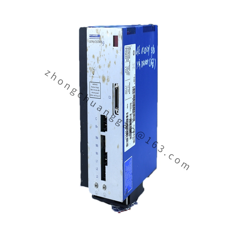
Cable Type: Motor Power + Brake Leads (if ordered) AND/OR Feedback (Resolver/Encoder) — CR10561 most commonly cited as Feedback / Resolver cable for Goldline B-series; confirm from cable label (POWER vs FEEDBACK tag)
Conductor Spec (Power — if power version): 4× power conductors AWG 18–AWG 16 (rated ≤ 20 A), brake pair AWG 22
Conductor Spec (Feedback — CR10561 typical): Twisted-pair screened wires AWG 24–AWG 22 — resolver: R1/R2 excitation + S1/S2/S3/S4 sine/cosine; encoder: A/A–, B/B–, Z/Z– + 5 V/GND + motor thermistor
Shielding: Overall tinned copper braid + AL-foil, drain wire terminated at drive-end connector shell
Jacket Material: PUR (Polyurethane) or PVC (region-dependent) — oil-resistant, flame-retardant per UL 20276 / IEC 60332-1
Rated Voltage: Power cores ≤ 600 V AC/DC; Signal cores ≤ 30 V DC
Temperature Range (Operation): –25 °C to +80 °C (PUR jacket)
Bend Radius (Static): ≥ 5 × OD; (Flex/Trailing Chain) ≥ 10 × OD
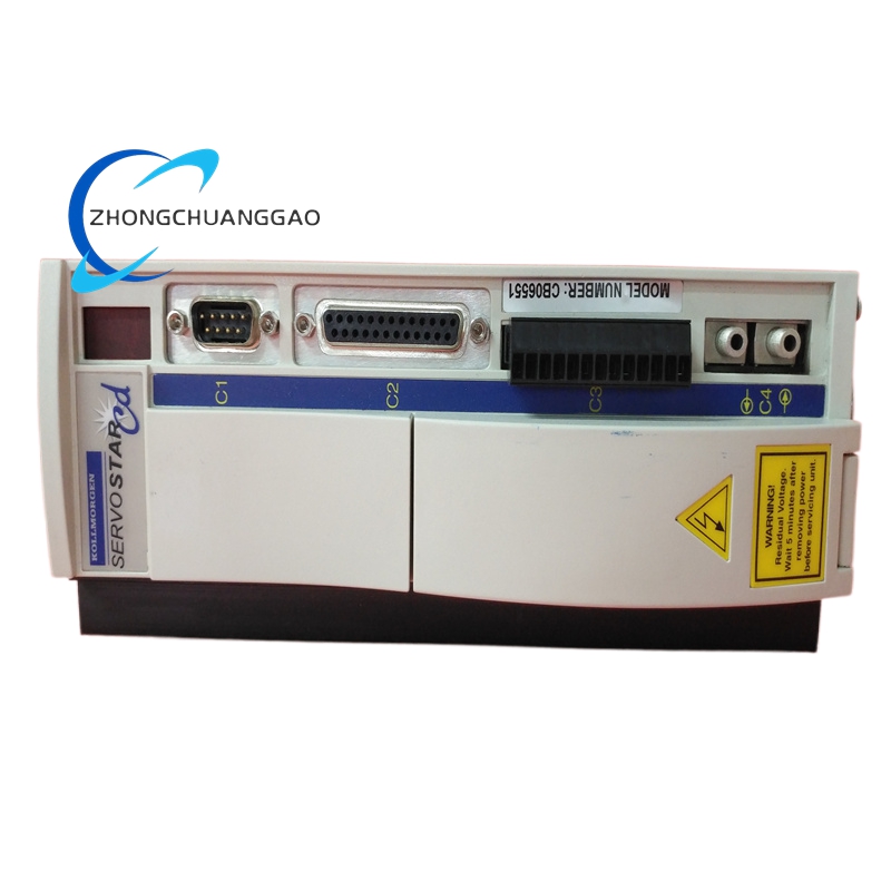
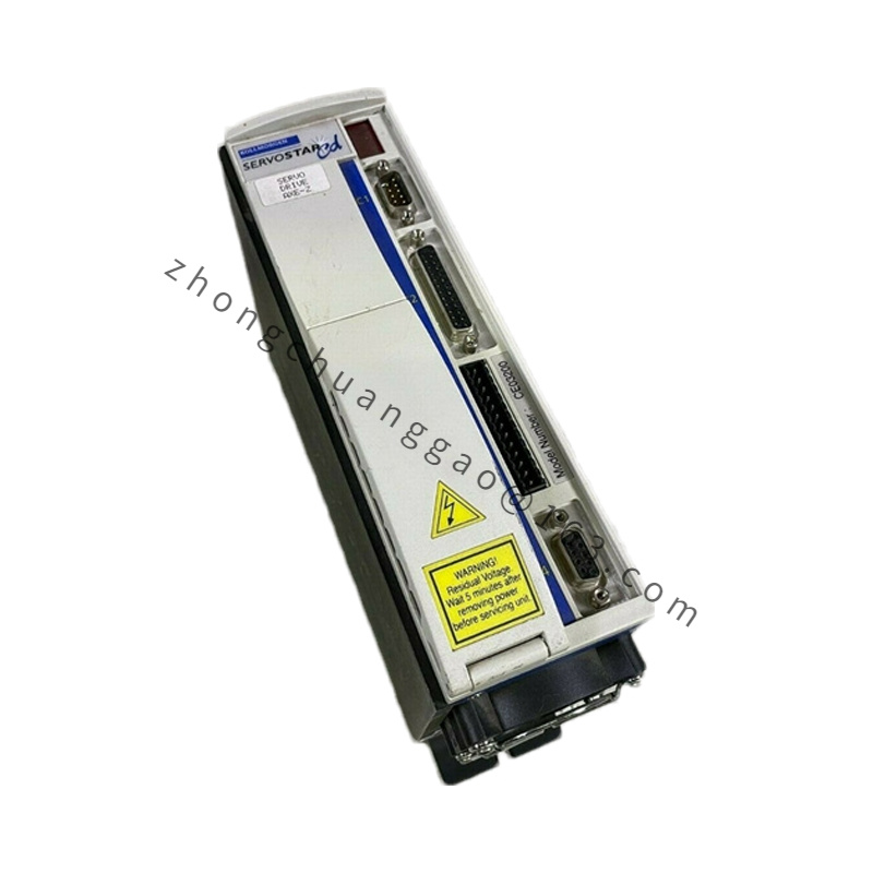
Connector (Motor End): M23 / Intercontec circular — keyed, rotatable, IP65 when mated
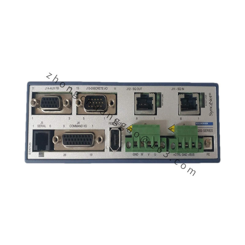
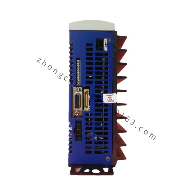
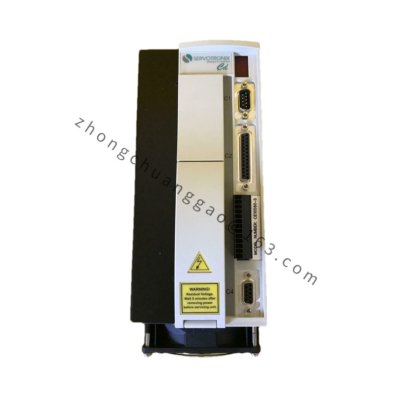
Connector (Drive End): Flying leads with ferrules OR pre-installed terminal-block plug / SUB-D (feedback) per SERVOSTAR I/O layout
Length: Defined by last digits of full order code (common: 3 m / 5 m / 7 m / 10 m)
Compliance: CE, UL recognized component, RoHS, DESINA color coding (where applicable)
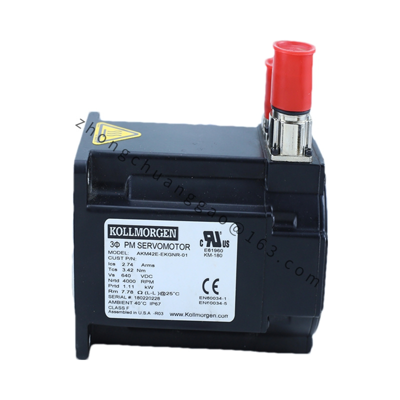
Applicable Industries: Legacy Goldline B/M-series equipped packaging, converting, printing, textile, machine tool retrofits
Installation Requirements: Route power and feedback cables separately from high-voltage mains (≥ 200 mm separation or partitioned duct); bond shield to drive chassis ground terminal only at one end (drive side); verify connector keyway before mating; avoid tight bend radii < 5× OD.
Usage Notes: CR-series cables are legacy — for AKM motors use CE/CP-prefix cables; if CR10561 is resolver feedback cable ensure pinout matches resolver type (2-pole single-speed standard on Goldline B); inspect O-ring on motor connector before mating to maintain IP65.


.jpg)