
Digital guide
You are here:
- Home
- Kollmorgen
- Kollmorgen B-404-D-21-B3
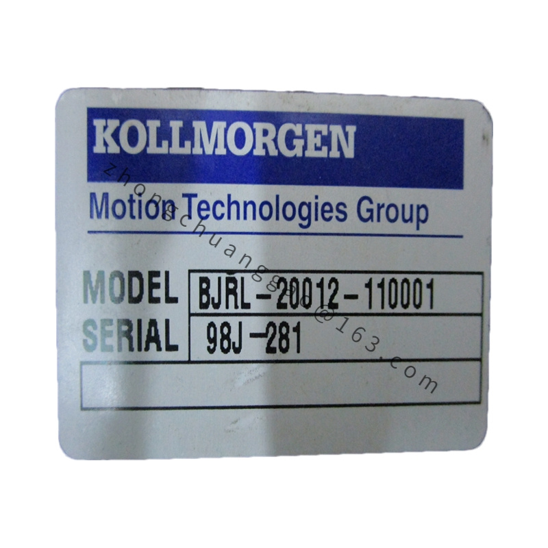
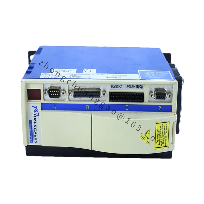
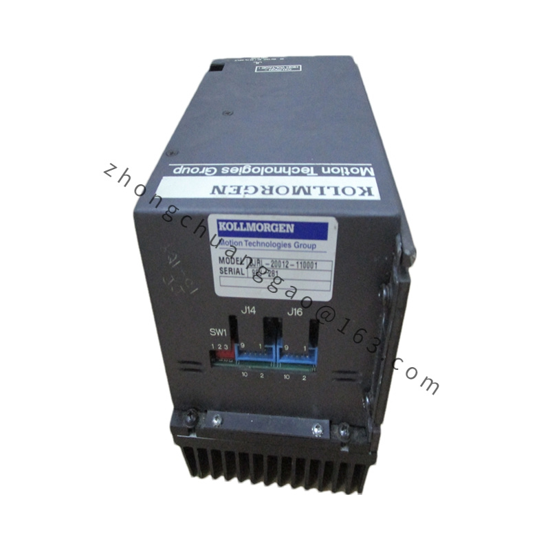
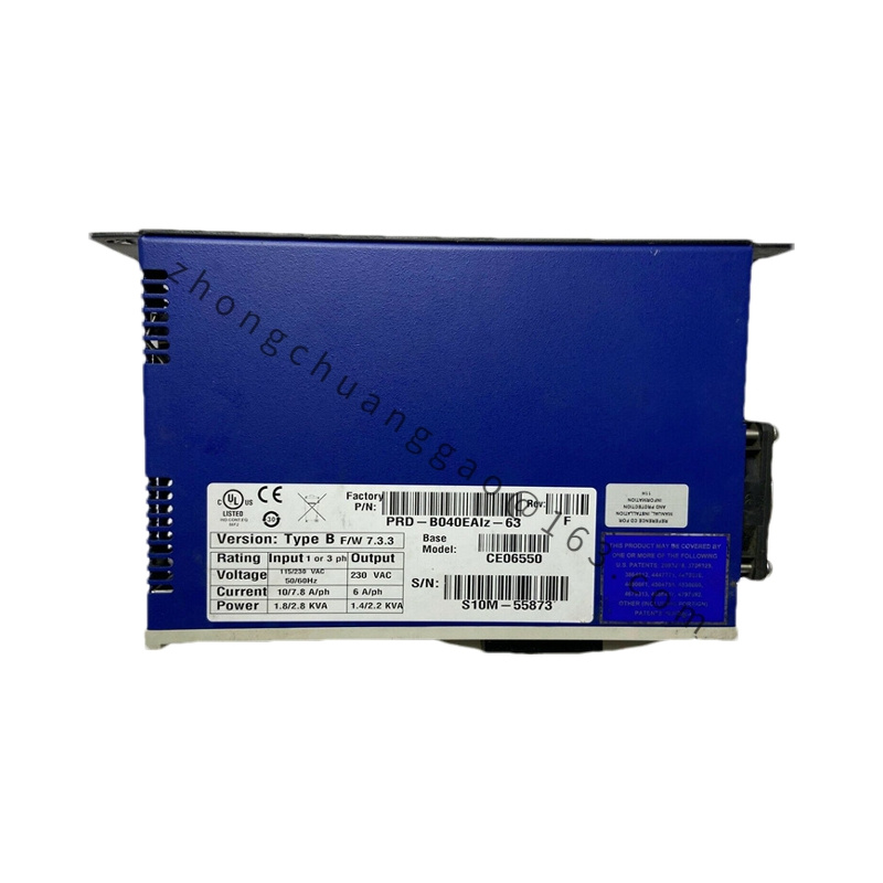
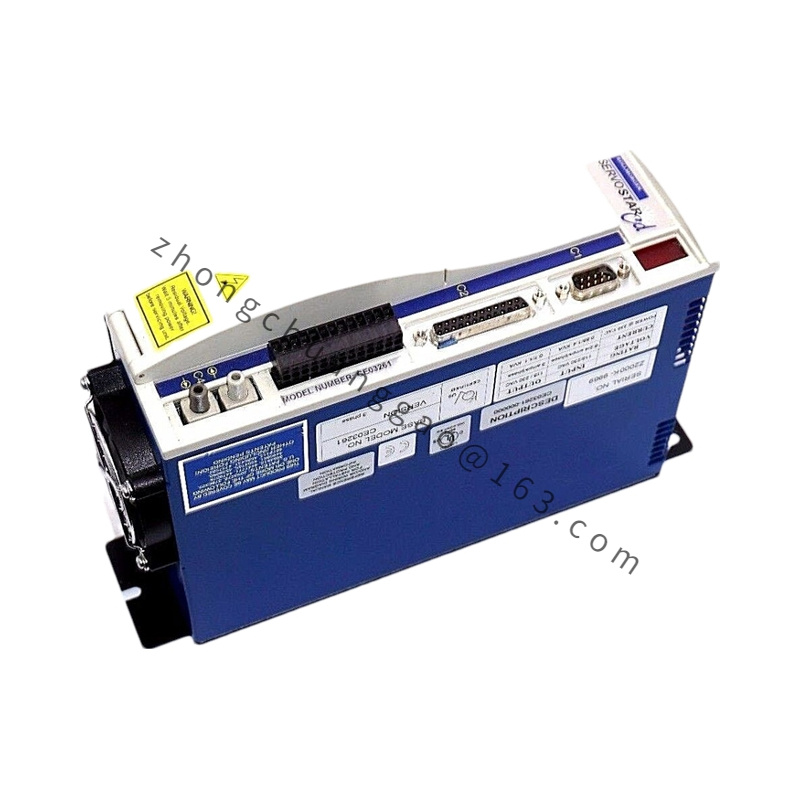
Kollmorgen B-404-D-21-B3
Product Brief Introduction
This unit is a compact frame-size industrial brushed DC servo motor designed for low-to-medium precision single-axis motion control. It integrates ferrite permanent magnet rotor, integral tachometer feedback, rear fan cooling structure, and standard NEMA mounting flange, exclusively matched with Kollmorgen legacy analog servo amplifiers. It delivers stable continuous torque under constant low-speed operating conditions for fixed-cycle automation equipment.
Detailed content
Technical Specifications
- Electrical Parameters
- Rated Input Voltage: 90 VDC
- Continuous Armature Current: 4.2 Arms
- Peak Armature Current: 12.6 Arms (3x overload, 5s max duration)
- Rated Power Output: 380 W
- Back EMF Constant: 0.072 V/RPM
- Torque Constant: 0.68 N·m/A
- Armature Winding Resistance: 2.15 Ω @ 25°C
- Armature Winding Inductance: 18.2 mH
- Mechanical Performance Parameters
- Continuous Rated Torque: 2.86 N·m
- Peak Torque: 8.58 N·m
- Rated Speed: 3000 RPM
- Maximum Mechanical Speed: 4500 RPM
- Rotor Inertia: 0.00041 kg·m²
- Torque Ripple: ≤ 3.2% of rated torque
- Environmental & Insulation Specs
- Insulation Class: F Class (155°C maximum winding temperature)
- Operating Ambient Temperature: -5°C ~ +40°C (derate 6% per 1000m altitude above sea level)
- Storage Temperature: -30°C ~ +70°C
- Protection Rating: IP54 housing, IP50 shaft extension
- Vibration Grade: Vibration Class 2 per IEC 60034-14
Functional Features
- Integrated analog tachometer generator (20 V/1000 RPM) for closed-loop speed regulation without digital encoders
- Carbon brush replaceable rear housing design for on-site maintenance
- Internal thermal PTC over-temperature sensor with 130°C trip threshold
- Standard 24VDC holding brake pre-wired (suffix B3 = spring-applied power-off brake configuration)
- Balanced rotor assembly to eliminate high-speed resonance noise
- Analog signal terminal block separated from power terminals for electromagnetic interference isolation
Working Principle
DC voltage input energizes stator wound field coils, generating static magnetic flux. The ferrite permanent magnet rotor interacts with stator flux to produce continuous rotary torque. The rear-mounted tachometer outputs proportional analog voltage corresponding to real-time shaft speed; the matched analog servo amplifier compares command speed signal against tachometer feedback voltage, dynamically adjusting armature current to eliminate speed deviation. The built-in power-off brake engages via spring force when DC brake supply cuts off, locking the output shaft to prevent load free fall.
Material Composition
- Stator Housing: Die-cast aluminum alloy ADC12 with black anti-corrosion powder coating
- Rotor Core: Cold-rolled silicon steel 0.35mm lamination stack
- Permanent Magnet: Hard ferrite magnet bonded to rotor surface
- Shaft: 4140 alloy steel, induction hardened, black oxide anti-rust treatment
- Brush Holder: High-temperature thermosetting plastic
- Brake Friction Disc: Graphite composite wear-resistant material
- Terminal Cover: ABS flame-retardant plastic UL94-V0
Structural Characteristics
- NEMA 34 standard front mounting flange with 4 through-hole installation points
- Single keyway output shaft, diameter 19.05mm
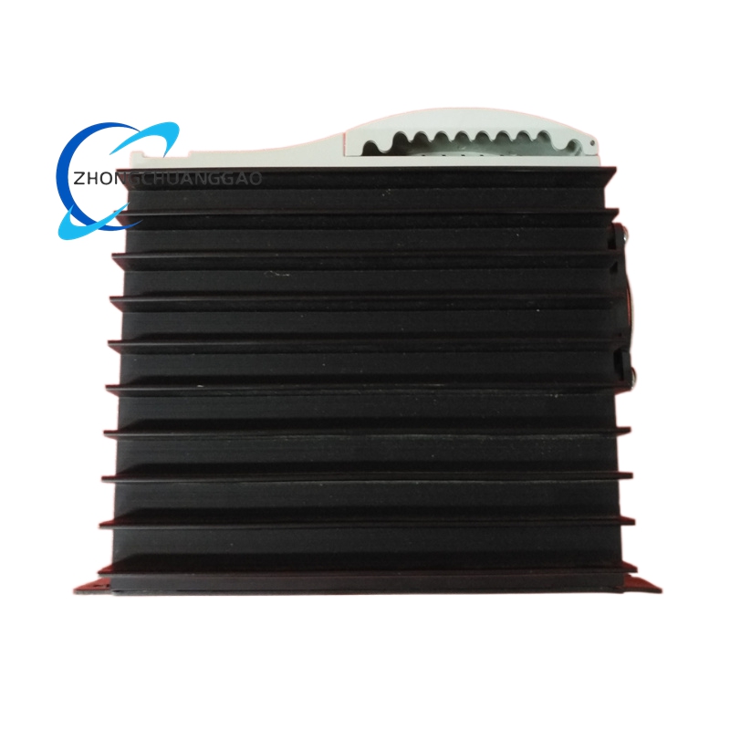
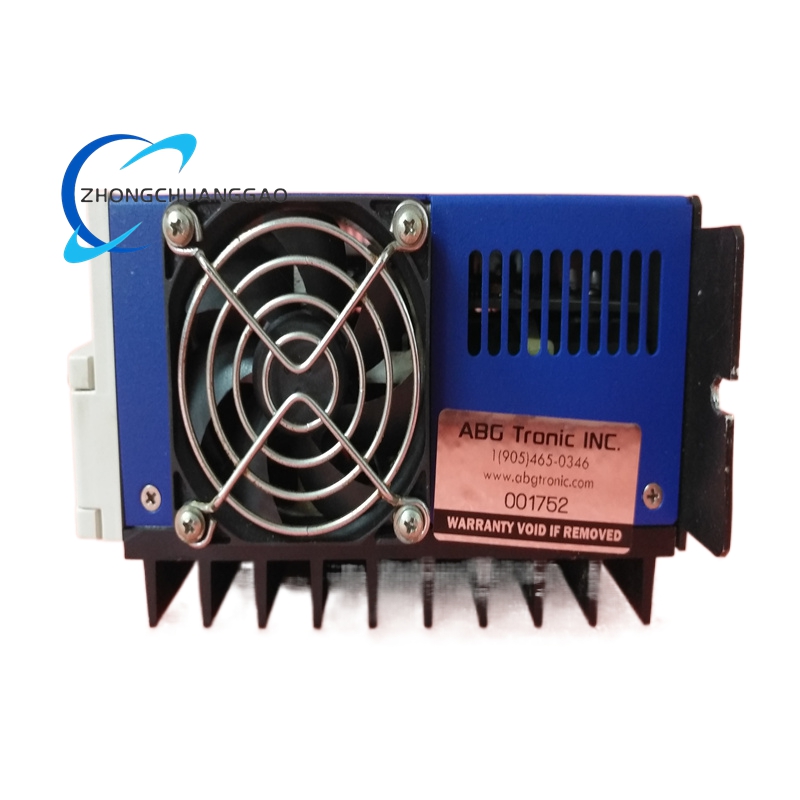
- Axial forced air cooling fan mounted at rear end cap
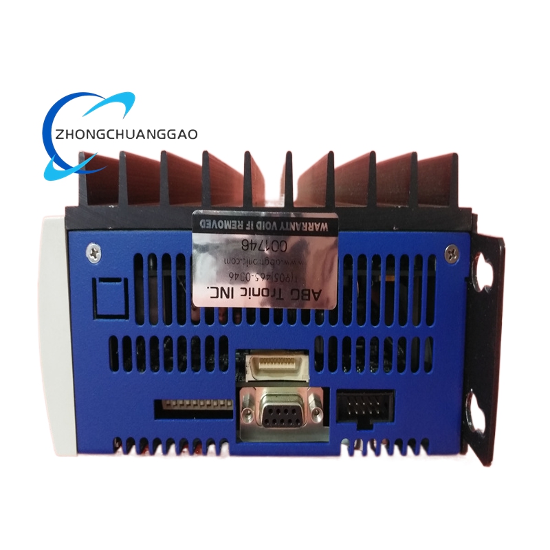
- Separated dual terminal compartments: power circuit & feedback/brake signal circuit
- Removable rear brush access panel without full motor disassembly
- Spring-applied static brake integrated between rotor core and rear fan assembly
Advantage Highlights
- Low procurement & maintenance cost compared to brushless servo motors
- Analog feedback architecture compatible with legacy analog motion control systems
- Wide constant-torque low-speed operating range without cogging torque distortion
- Replaceable carbon brushes extend total service life to 20,000 operating hours
- Built-in holding brake eliminates external shaft locking mechanism requirements
- High shock resistance against short-duration overload torque spikes
Applicable Industries
Conveying automation, packaging auxiliary machinery, textile looms, printing press auxiliary axes, laboratory test equipment, low-speed positioning fixtures, vintage analog machine tool retrofits
Installation Requirements
- Mount via 4 flange bolts with tightening torque of 12 N·m; mounting surface flatness tolerance ≤ 0.05mm per 100mm
- Maintain minimum 50mm clearance at rear fan end cap for unobstructed cooling airflow
- Install motor with horizontal shaft orientation; vertical mounting requires additional shaft thrust bearing support
- Power cable shielding must be grounded to equipment chassis at single termination point only
- Brake circuit wiring separated from armature power wiring with minimum 10mm spacing to avoid signal interference
Operation Precautions
- Continuous operation above 40°C ambient requires 15% torque derating
- Do not exceed peak current duration limit of 5 seconds to prevent permanent winding insulation damage
- Replace carbon brushes when remaining length reduces to 3mm to avoid rotor commutator scoring
- Brake supply voltage must maintain ±5% tolerance; under-voltage causes incomplete brake release
- Avoid repeated rapid forward/reverse rotation cycling exceeding 5 cycles per second to reduce brush wear rate
- Prevent liquid, conductive dust or metal shavings from entering rear fan ventilation slots

.jpg)