")

Digital guide
You are here:
- Home
- Kollmorgen
- Kollmorgen B-202-C-23-096
Kollmorgen B-202-C-23-096
Product Overview
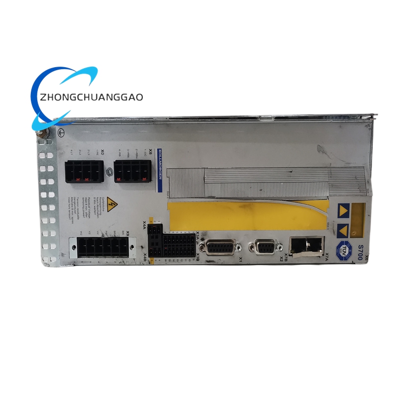
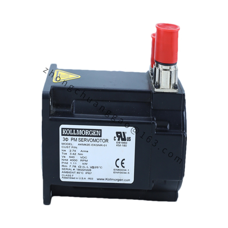
Medium-size industrial brushless synchronous servo motor with high torque density design, built for continuous high-load operation, matched to S700 and SERVOSTAR series high-voltage servo drives. Standard resolver feedback, optional holding brake, IP65 full shaft/body protection for harsh factory environments.
Detailed content
Core Technical Specifications
- Rated Supply Voltage: 400 VAC three-phase matching S700 series drives
- Continuous Rated Torque: 23 N·m
- Peak Torque (3s Overload): 69 N·m (300% overload capacity)
- Nominal Rated Speed: 3000 RPM
- Rated Continuous Power Output: 7.2 kW
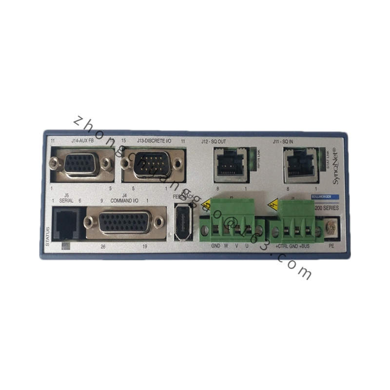
- Feedback Device Definition (-23 suffix): Single-turn analog sine/cosine resolver, 2-pole
- Shaft & Flange Code (-096 suffix): 96 mm square standard IEC mounting flange, smooth solid output shaft without keyway
- Winding Configuration (-C suffix): Standard high-speed low-inductance stator winding
- Rotor Magnet Material: Sintered neodymium iron boron permanent magnet
- Insulation Class: Class F (155°C maximum winding temperature)
- Mechanical Protection Grade: IP65 motor housing, shaft seal IP65
- Environmental Operating Range: -20°C ~ +40°C ambient temperature; Max operating altitude 1000 m (6% torque derate per 1000 m elevation)
- Vibration Compliance: DIN EN 60034-14 Class N
- Mechanical Dimensions: 96 mm flange width, overall motor length 285 mm
- Net Motor Weight: 12.8 kg
Function Features
- Three-phase brushless synchronous FOC vector control compatible with all Kollmorgen high-voltage servo drives
- High overload torque capacity handles instantaneous heavy acceleration load surges
- Standard analog resolver feedback immune to electromagnetic interference in high-noise factory environments
- Optional integral spring-applied power-off holding brake for vertical axis load locking
- Standard double lip shaft oil seal prevents coolant, dust and liquid ingress
- Uniform stator winding temperature distribution eliminates local hot-spot burnout
- Low cogging torque design (<1% rated torque) delivers ultra-smooth low-speed rotation
Performance Highlights
- High torque density neodymium rotor reduces overall motor length compared to equivalent torque competitors
- Class F high-temperature insulation sustains continuous full-load operation without winding degradation
- Resolver feedback maintains stable position signal under welding, inverter high EMI factory conditions
- Wide speed operating range from 0 RPM stall to 3000 RPM rated speed without torque drop-off
Material & Structural Characteristics
- Motor stator housing: Cast aluminum alloy with external cooling rib structure
- Rotor core: Laminated silicon steel sheet stack bonded with high-temperature epoxy
- Permanent magnet: Sintered NdFeB magnet with anti-demagnetization surface coating
- Shaft material: High-strength alloy steel quenched and tempered, corrosion passivation treatment
- Bearing assembly: Double-row sealed grease-lubricated ball bearings, lifetime maintenance-free design
- Terminal housing: Flame-retardant nylon plastic with IP65 cable gland sealing
Working Principle
Three-phase variable frequency sinusoidal current output from matched servo drive flows through stator distributed windings to generate rotating magnetic field. Rotor embedded neodymium permanent magnet interacts with stator rotating field to produce continuous electromagnetic torque driving output shaft rotation. Resolver mounted at motor rear end detects real-time rotor electrical angle, feeds analog sine/cosine position signal back to servo drive to close triple control loop, realizing precise speed and position regulation. Optional holding brake engages via spring force when power cut off to lock shaft position for vertical load safety.
Applicable Industries
Metal cutting CNC machinery, automated stamping lines, printing rotary equipment, packaging heavy conveyor axes, plastic injection molding servo axes, woodworking gantry machines, hydraulic press electric servo retrofits
Installation Requirements
- Horizontal or vertical flange mounting allowed; vertical shaft downward mounting requires drain plug installation
- Mounting surface flatness tolerance ≤0.02 mm per 100 mm flange area
- Align motor shaft with load coupling concentricity tolerance ≤0.05 mm radial runout
- Power and feedback cables adopt shielded servo cable, cable gland fully tightened to maintain IP65 seal
- Motor housing PE ground terminal connected to machine frame with minimum 4 mm² copper wire
Operation Precautions
- Do not operate motor above 3000 RPM rated maximum speed to avoid bearing premature wear
- Avoid continuous stall operation exceeding 10 seconds to prevent stator winding overheating
- Prevent direct coolant splash onto motor terminal housing in machining environments
- Brake-equipped variants require dedicated brake power supply circuit per drive manual
- Annual bearing grease inspection required for 24-hour continuous production operation