Digital guide
You are here:
- Home
- Kollmorgen
- Kollmorgen B-202-B-23
Kollmorgen B-202-B-23
Product Introduction:
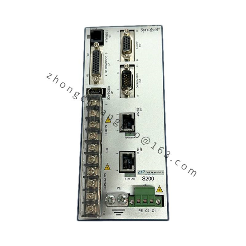
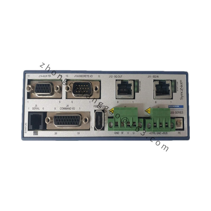
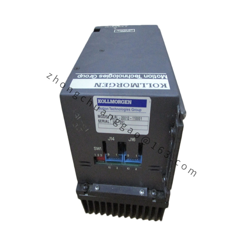
The B-202-B-23 is a spring-applied, electrically-released (fail-safe) electromagnetic holding brake designed for use with Kollmorgen B-Series and AKM-Series servo motors. It provides positive mechanical holding torque when power is removed, ensuring the load remains stationary during power loss or emergency stop conditions. This is a critical safety component for vertical-axis applications and any system requiring fail-safe position retention.
Detailed content
Technical Specifications:
| Parameter | Value |
|---|---|
| Brake Model | B-202 |
| Configuration | B-23 |
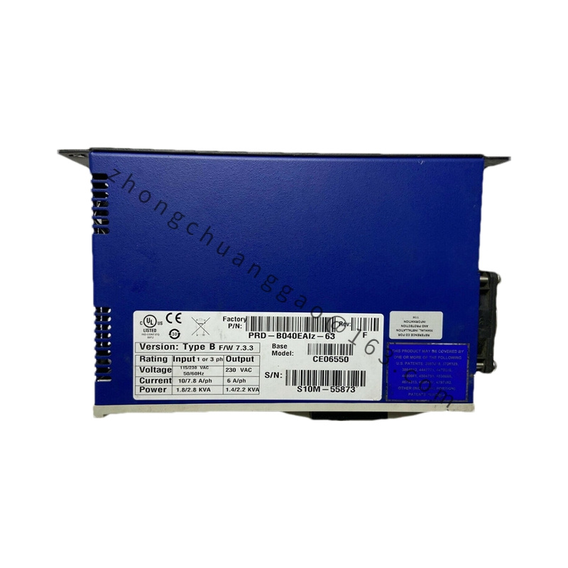
| Rated Voltage | 24 VDC |
| Holding Torque | 2.0 Nm (Nominal) |
| Release Time | <20 ms (Typical) |
| Engage Time | <30 ms (Typical) |
| Power Consumption (Holding) | 0 W (Spring-Applied) |
| Power Consumption (Released) | ~4 W (24 VDC) |
| Duty Cycle | 100% (Continuous Holding) |
| Operating Temperature | -20°C to +70°C |
| IP Rating | IP54 (with proper sealing) |
| Weight | ~0.35 kg |
| Compliance | CE, UL, RoHS |
Functional Features:
- Spring-applied / Electrically-released: Brake engages automatically on power loss (fail-safe)
- Zero power holding: No continuous current required to maintain hold — eliminates thermal buildup
- Fast release/engage cycle for high-dynamic applications
- Manual release lever for maintenance and setup without power
Structural Features:
- Friction Material: Sintered metallic compound for consistent torque over lifetime
- Armature Plate: High-permeability electrical steel
- Coil: Copper windings with Class H insulation (180°C)
- Housing: Zinc-plated steel with corrosion-resistant coating
- Mounting: Direct bolt-on to motor rear flange (compatible with B-Series motor mounting pattern)
Advantages:
- Fail-safe operation — load held on power failure with zero standby power
- High cycle life (>10 million operations)
- No brake wear during holding (spring force, not friction, holds load)
- Compact design integrates directly onto motor flange
Applicable Industries:
- Vertical-axis robots (Z-axis holding)
- CNC machine spindle brakes
- Conveyor systems (emergency stop holding)
- Elevators and lifts
- Packaging machines (cut-and-seal hold)
Installation Requirements:
- Mount brake to motor rear flange using 4× M5 socket head cap screws
- Torque mounting bolts to 2.0 Nm
- Wire brake coil to 24 VDC control output from servo drive (brake release signal)
- Ensure minimum 0.5 mm air gap between armature and friction disc at release
Usage Notes:
- Verify brake release voltage matches drive output (24 VDC nominal)
- Do not operate brake at voltages exceeding 28 VDC (115% of rated)
- Inspect friction disc thickness every 10,000 hours of operation; replace when worn to 50% of original thickness


