
Digital guide
You are here:
- Home
- Kollmorgen
- Kollmorgen AKD-B01206-NCS
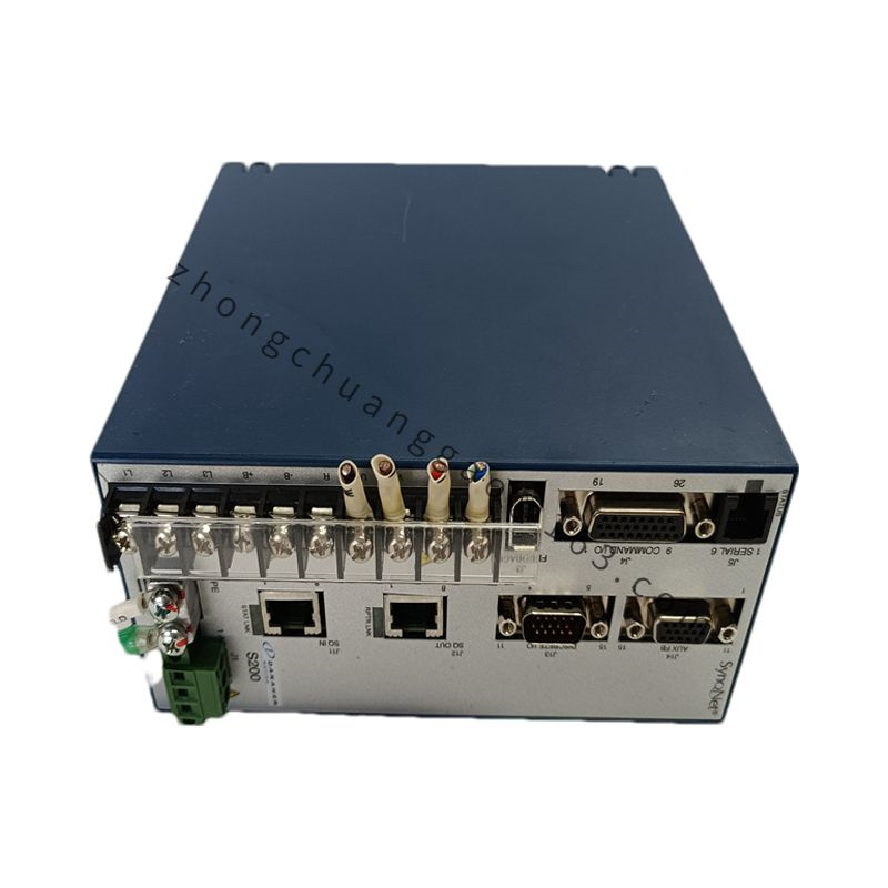
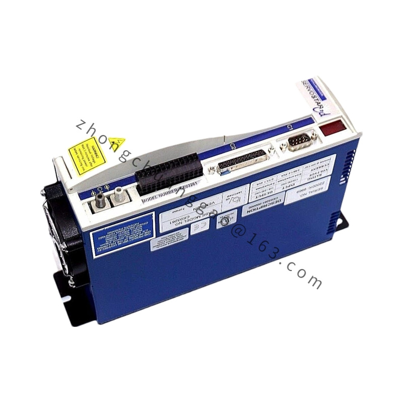
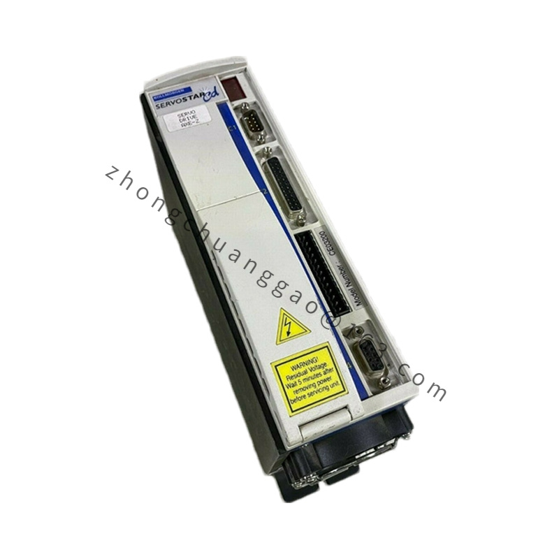
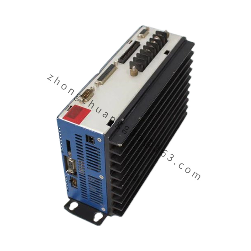
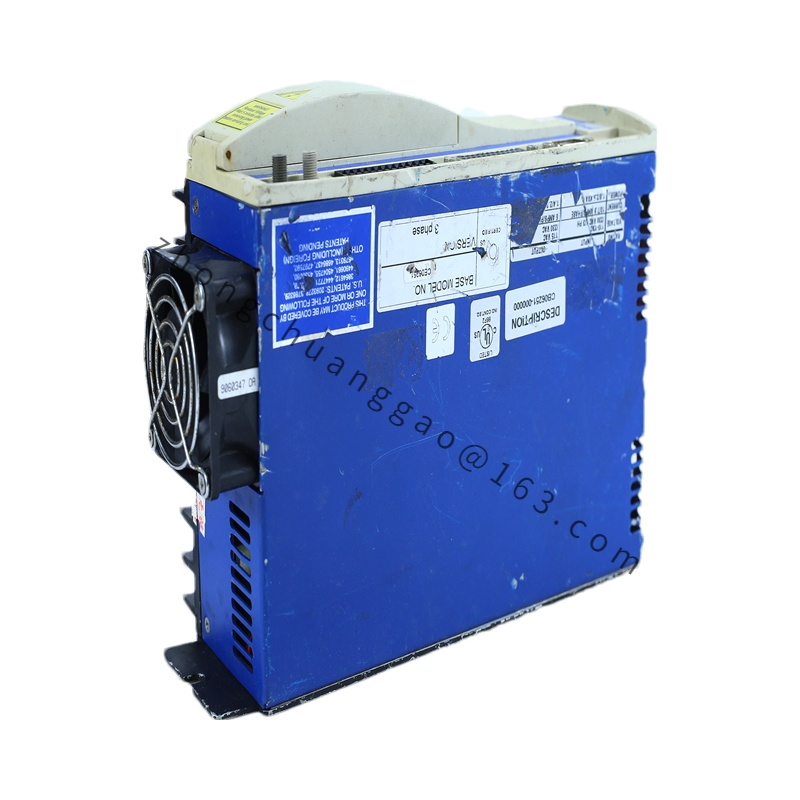
Kollmorgen AKD-B01206-NCS
Product Overview
AKD-B01206-NCS is baseline low-voltage DC digital servo drive under Kollmorgen AKD series. Model decoding: AKD-B = Baseline cost-effective low-voltage variant; 012 = 12A continuous DC output current rating; 06 = 48VDC low voltage hardware base; suffix NCS = native CANopen bus, SFD single-cable feedback interface, standard digital I/O configuration without STO safety module or Ethernet expansion card.
Detailed content
Technical & Performance Specifications
- DC Bus Input Voltage: 24–80 VDC regulated isolated power supply
- Continuous Phase Output Current: 12 Arms RMS
- Peak Overload Output Current: 30 Arms RMS, sustainable for maximum 5 seconds (250% continuous overload capacity)
- Rated Output Power: 1.8 kW at 48VDC input
- Velocity Loop Maximum Bandwidth: 1500 Hz
- PWM Switching Frequency: 20 kHz ultra-high frequency modulation
- Control Loop Refresh Rates: Current loop 50 μs, Velocity loop 100 μs, Position loop 200 μs
- Standard Communication Interfaces (NCS suffix): CANopen DS402, RS232 WorkBench diagnostic port
- Feedback Compatibility (S suffix): SFD single-cable servo feedback, incremental sine/cosine encoders, resolvers
- Analog I/O Channels: 2 × ±10VDC differential analog input, 1 × analog output
- Digital I/O Channels: 6 × 24VDC sinking/sourcing isolated input, 3 × isolated open-collector output
- Dynamic Braking Hardware: Onboard integrated internal braking resistor for low-inertia load regeneration absorption
- Complete Protection Suite: Overcurrent, DC bus overvoltage/undervoltage, PCB heatsink overtemperature, motor thermal fault, feedback signal loss, output short circuit, earth leakage interlock
- Cooling Method: Passive PCB copper plane + mini aluminum fin natural convection fanless cooling
- Protection Class: IP20, cabinet DIN rail mounting only
- Net Weight: 0.45 kg
- Outer Dimensions (W × H × D): 30 mm × 160 mm × 125 mm
Material Composition
- Outer Housing: Thin extruded black anodized 6063 aluminum alloy mini frame
- Main Control PCB: High-density miniaturized FR4 flame-retardant lead-free circuit board
- Power Stage Module: Surface-mount three-phase MOSFET power bridge thermally bonded to integrated aluminum fin radiator
- Terminal Connectors: Small PA66 insulated copper spring-clamp quick-disconnect terminals
- Dynamic Brake Resistor: Miniature ceramic encapsulated wire-wound power resistor
- EMI Shield Partitions: Thin cold-rolled steel shielding separating power and signal PCB zones
Structural Features
- Ultra-slim 30mm width vertical DIN rail form factor, minimal cabinet horizontal space occupation
- Unified passive cooling structure combining PCB copper thermal plane and external aluminum fin array without cooling fan assembly
- Front panel fully segmented terminal layout: DC power, motor power, SFD feedback, CANopen bus, digital/analog I/O separated by internal metal shielding barriers
- Onboard non-volatile flash memory preloaded with full AKM low-voltage motor parameter library for one-click auto-tuning
- No factory pre-installed STO safety circuit or Ethernet expansion slots on NCS baseline variant
- Compact spring-clamp terminals support rapid wiring without torque screwdriver calibration
Working Principle
External regulated 24–80VDC isolated DC power supply feeds drive DC bus circuit to supply three-phase MOSFET power inverter stage. High-speed DSP motion controller processes CANopen real-time motion commands or analog ±10V torque/velocity setpoints, sampling SFD single-cable encoder rotor position feedback at 20kHz PWM cycle. Triple closed-loop PI-PDFF control algorithms dynamically adjust sinusoidal three-phase output current to eliminate linear and rotary positioning tracking deviation. During load deceleration regenerative energy is dissipated by internal dynamic braking resistor to stabilize DC bus voltage. Continuous multi-channel fault monitoring circuit samples all electrical and thermal operating parameters, executing instant power stage hardware cut-off upon fault threshold violation to protect drive and matched low-voltage AKM servo motor hardware.
Function Features
- Pre-stored full parameter database for all AKM low-voltage 24–80VDC servo motors, cutting commissioning time by 70%
- 20kHz ultra-high PWM frequency suppresses low-speed torque ripple below 0.6% rated continuous torque
- Native SFD single-cable feedback interface reduces wiring count between drive and servo motor by 50%
- Integrated dynamic braking resistor eliminates external brake resistor accessory requirement for low/medium inertia loads
- Built-in adaptive digital anti-resonance filter suppresses miniature mechanical axis vibration and audible noise
- Spring-clamp quick-disconnect terminals reduce field wiring assembly labor
- RS232 multi-drop diagnostic port supports batch parameter backup, restore and firmware upgrade via Kollmorgen WorkBench software
Advantage Highlights
- Fanless passive cooling design eliminates fan failure, dust clogging and regular fan maintenance points
- Ultra-slim 30mm width DIN rail chassis enables dense multi-axis compact cabinet layouts
- Low-voltage 24–80VDC DC input compatible with battery-powered mobile automation equipment
- SFD single-cable feedback architecture halves wiring material and assembly cost compared to dual separate power/feedback cables
- CE, UL/cUL, RoHS global compliance certification for OEM small automation mass production
- 1500Hz velocity loop bandwidth delivers ultra-fast dynamic response for miniature pick-and-place axes
Applicable Industries
Mobile battery-powered robotic equipment, laboratory micro-positioning stages, desktop engraving machinery, medical portable diagnostic automation, miniature packaging labeling axes, optical inspection compact positioning platforms, small 3D printing motion control systems
Installation Requirements
- Mandatory vertical DIN rail cabinet mounting orientation; horizontal mounting reduces heat dissipation efficiency by 42%
- Minimum unobstructed airflow clearance: 50 mm vertical space above drive top edge, 30 mm lateral side clearance
- DIN rail mounting metal backplane connected to equipment star earth grid via ≥2.5 mm² copper protective earth wire
- Motor power cable specification: ≤10 m length use 1.0 mm² four-core fully shielded copper cable
- SFD single-cable feedback wiring: Factory specified shielded single cable, maximum transmission distance limited to 50 m
- CANopen bus wiring: Twisted-pair shielded bus cable with 120Ω terminating resistor at network two endpoints
- Cable separation rule: DC power cables and low-level signal/communication cables routed in independent cable ducts; cross routing only at strict 90-degree perpendicular angle
Operation & Maintenance Precautions
- Cabinet ambient operating temperature range strictly limited to 0°C ~ +40°C; temperature above 40°C requires linear 15% continuous output current derate per 10°C temperature rise
- Monthly maintenance: Use clean compressed dry air to blow dust accumulated on external aluminum cooling fins
- Disconnect all external DC power supply and wait minimum 3 minutes for DC bus capacitor full discharge before disassembling terminal wiring
- Prohibit connecting servo motors with rated power exceeding 1.8 kW to avoid permanent MOSFET power stage thermal damage
- All SFD and CANopen cable shielding layers must implement double-end grounding to eliminate signal noise and position jitter
- Storage environment must maintain non-condensing relative humidity ≤85%; prohibit deployment in conductive dust or oil mist atmospheres
- Firmware upgrade and parameter configuration must exclusively use official Kollmorgen WorkBench software