Digital guide
You are here:
- Home
- Kollmorgen
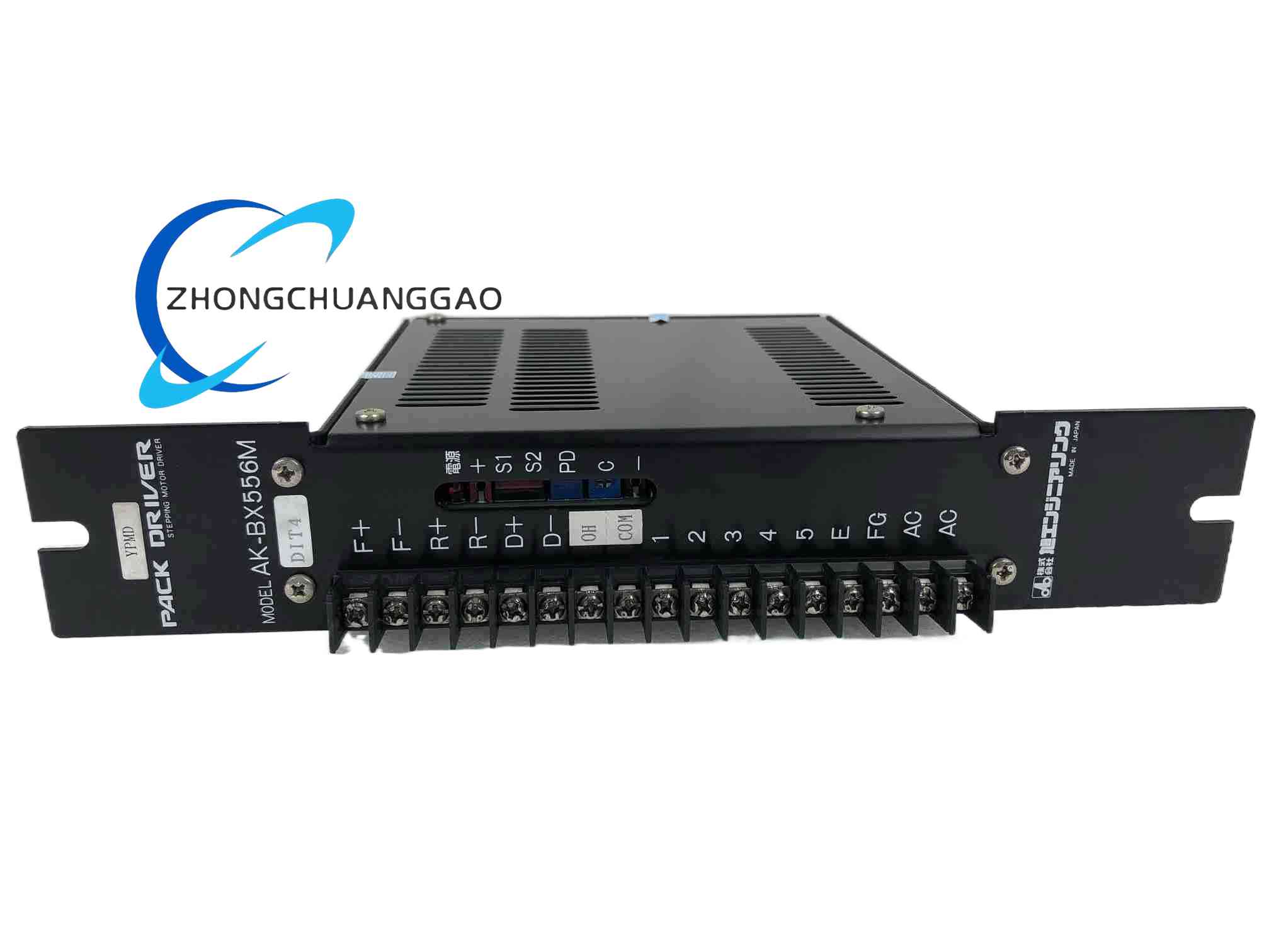
- KOLLMORGEN AK-BX556M
Detailed content
Technical Specifications
- Cable assembly: motor power, brake, and feedback combined
- Power conductors: four conductors, including three-phase power and protective earth
- Brake conductors: two conductors
- Feedback conductors: nine signal pairs
- Power conductor cross-sectional area: 1.5 mm², AWG 16
- Signal conductor cross-sectional area: 0.25 mm², AWG 24
- Power voltage rating: 600 V
- Signal voltage rating: 30 V
- Continuous current rating: up to 16 A at 30 °C ambient temperature
- Motor-end connector: Kollmorgen proprietary circular connector
- Minimum bending radius, fixed installation: 7.5 times the cable outer diameter
- Minimum bending radius, flexible installation: 10 times the cable outer diameter
- Operating temperature, fixed: -20 to +80 °C
- Operating temperature, flexible: -5 to +70 °C
- Shielding coverage: tinned copper braid, minimum 85%
- Signal pair shielding: individual foil shields
- Mating face protection rating: IP65
Function Features
- Combined power, brake, and feedback cabling
- Reduced wiring and cabinet entry points
- Individually shielded feedback pairs
- Overall braided shield for electromagnetic compatibility
- Color-coded conductors for identification
- Pre-tested cable assembly
- Suitable for drag-chain or flexible motion applications
Application Scenarios
- Packaging machines
- Assembly automation
- Material handling systems
- Robotics
- Machine tools
- Servo axes using Kollmorgen AKM motors and compatible drives
Performance Parameters
- Continuous current capacity: 16 A at 30 °C ambient
- Power rating: 600 V
- Signal rating: 30 V
- Shield coverage: minimum 85%
- Cable bend radius: 7.5 × cable diameter fixed; 10 × cable diameter flexing
Material Composition
- Tinned copper power and signal conductors
- PVC or industrial cable insulation and sheath
- Tinned copper braided shield
- Aluminum-polymer foil shields for signal pairs
- Proprietary circular connectors
- Strain-relief and cable-entry components
Structural Features
- Multi-conductor composite cable
- Separate power, brake, and feedback elements
- Overlapping overall shield
- Individually shielded feedback pairs
- Factory-fitted motor and drive connectors
- Flexible industrial cable construction
Working Principle
Three-phase conductors deliver drive output current to the motor stator. The brake conductors supply the holding brake circuit. Feedback pairs carry position, commutation, or resolver signals between the motor and drive. Shields reduce electromagnetic interference and provide a controlled grounding path for electrical noise.
Installation Requirements
- Route the cable away from main power conductors and high-voltage busbars.
- Do not exceed the minimum bending radius.
- Install suitable cable glands to maintain the rated ingress protection.
- Bond the shield correctly at the cabinet entry point.
- Connect the protective earth conductor at the required termination points.
- Leave an appropriate service loop at both ends.
Usage Precautions
- Do not splice or extend the cable in the field.
- Verify connector alignment before mating.
- Do not use the cable beyond its voltage, current, temperature, or bending rating.
- Inspect connectors for damaged pins or contamination before installation.
- Replace the cable if the jacket, shield, or connectors are damaged.