

Digital guide
You are here:
- Home
- Kollmorgen
- Kollmorgen S70102-NA
Kollmorgen S70102-NA
Product Introduction
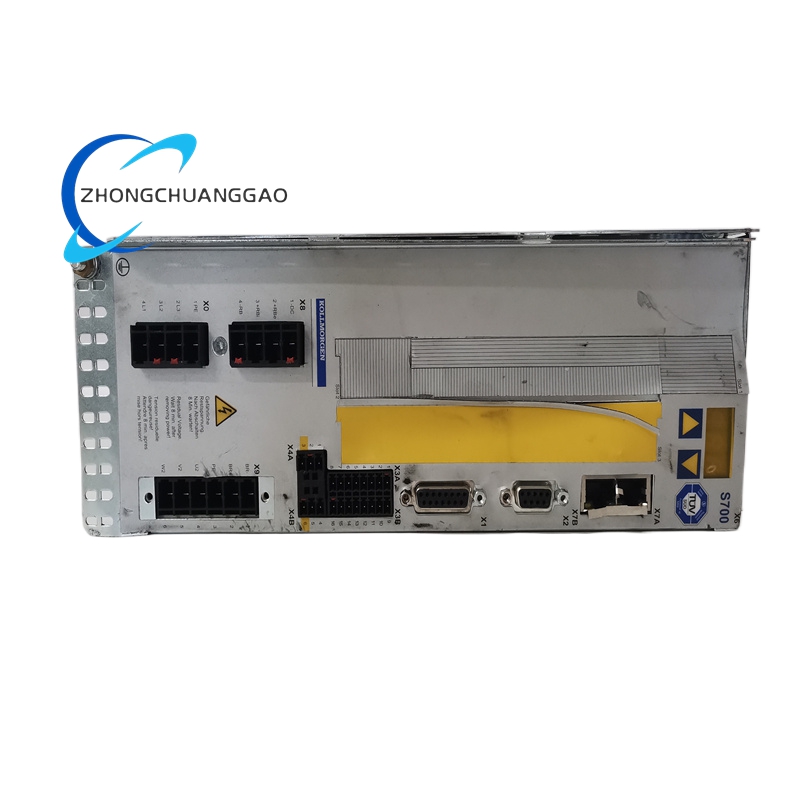
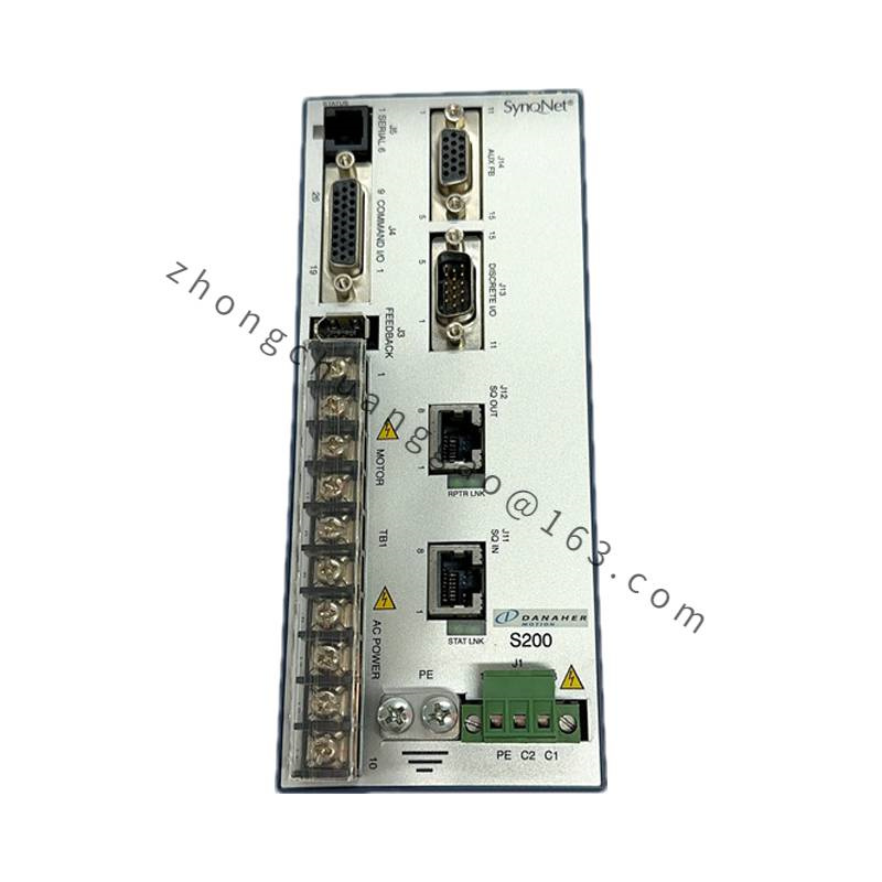
Full-digital compact low-power single-axis servo amplifier of Kollmorgen S700 platform, NA suffix denotes standard global universal mains hardware configuration without regional voltage limitation. Optimized for micro low-inertia AKM series servo motors, integrates complete SIL3 STO safety circuit and full set of mainstream industrial fieldbus interfaces, designed for small precision automation equipment with limited cabinet installation space.
Detailed content
Technical Specifications & Core Performance Parameters (Bold Key Data)
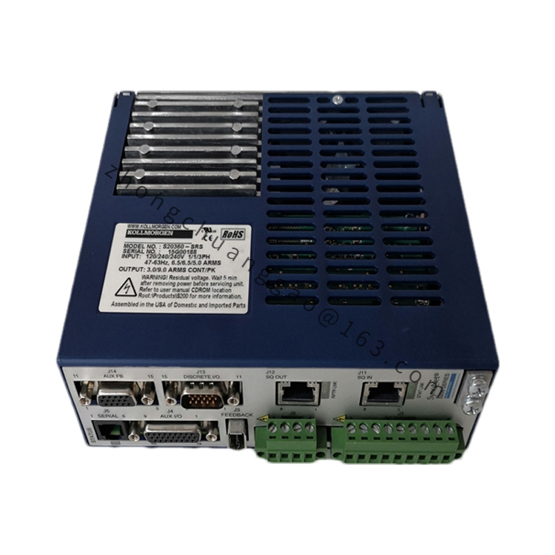
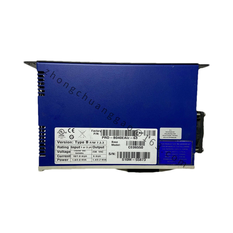
- Input Power Rating: Single/Three-Phase AC 115V / 230V, 50/60Hz global wide mains input
- Rated Continuous Output Current: 2.0 Arms
- Peak Output Current: 6.0 Arms (2-second maximum sustain)
- Nominal Matching Motor Power: 0.75kW / 1.1kW two power matching tiers
- DC Bus Operating Range: 160VDC ~ 455VDC; Overvoltage fault threshold 455VDC, Undervoltage fault threshold 100VDC
- PWM Switching Frequency: 8kHz fixed output stage frequency
- Control Loop Refresh Cycles: Current Loop 62.5μs, Speed Loop 62.5μs, Position Loop 250μs
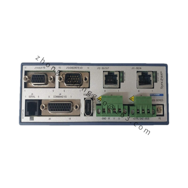
- Supported Feedback Signals: Resolver, EnDat 2.1/2.2, BiSS-C, HIPERFACE, SFD3 single-cable feedback, incremental encoder, SSI absolute encoder
- Onboard Standard Communication Interfaces: EtherCAT, CANopen, DeviceNet, PROFIBUS, SERCOS 2, analog ±10V command, pulse/direction input
- Safety Certification Grade: SIL3 / PLe (EN 61508, EN 60204-1); dual-channel independent STO safety torque shutoff circuit
- Physical Dimension: W 50mm × H 345mm × D 243mm
- Net Weight: 3.6kg
- Protection Class: IP20, cabinet internal installation only
- Operating Ambient Temperature: 0°C ~ +40°C full rated output; 40°C ~ 55°C linear derate 2.5% per °C
- Storage Temperature Range: -25°C ~ +55°C
- Allowable Relative Humidity: ≤85%, zero condensation permitted
- Max Operating Altitude: 1000m without power derating; 6% power reduction per additional 1000m elevation
Material Composition
- Outer Housing: Cold-rolled steel plate with black matte anti-corrosion electrophoretic coating
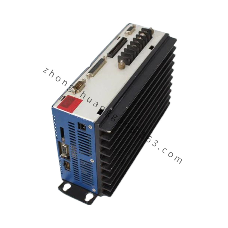
- Power Heat Sink: Extruded high-purity aluminum alloy finned passive cooling structure
- Main Control PCB: FR-4 high-temperature resistant fiberglass substrate, lead-free industrial grade solder
- Power IGBT Module: Silicon insulated gate bipolar transistor with built-in temperature detection thermistor
- Terminal Connectors: Nickel-plated copper conductive terminals, flame-retardant PA66 plastic insulation shell
- Internal EMC Components: Metal film suppression capacitors, high-permeability ferrite ring inductors
Structural Features
- Ultra-narrow vertical DIN rail mounting structure, compatible with standard 35mm cabinet mounting rails
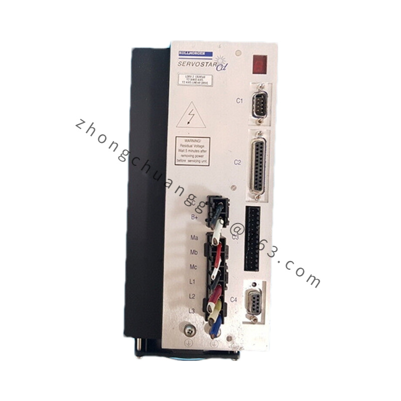
- Physical partition isolation between upper weak current signal zone and lower high-power terminal zone to eliminate cross-circuit interference
- Front panel multi-color LED indicator array: Power Supply, System Fault, Fieldbus Communication, STO Safety Trigger, Axis Running Status
- Front embedded SD card slot for offline parameter backup, firmware batch upgrade without upper computer connection
- Internal layered metal shielding partition completely separates power drive circuit and low-amplitude feedback signal circuit
- Integrated built-in standard regenerative braking resistor module, meets basic deceleration energy consumption demand without external accessories
Working Principle
- AC mains input flows through built-in EMC filter and full-wave rectifier to generate stable DC bus voltage for IGBT power drive stage
- 32-bit floating-point DSP processor executes high-speed triple closed-loop control algorithm, receives real-time rotor position signal from feedback encoder to dynamically adjust three-phase PWM output current amplitude and phase
- Integrated multi-protocol bus communication chip realizes real-time data interaction with upper PLC or motion controller, supporting electronic cam, electronic gear and flying shear motion logic
- Dual independent hardware STO circuit directly cuts IGBT gate drive signal upon safety signal trigger, achieves zero motor torque output within 2μs, independent of software operation state
- Real-time monitoring circuit continuously samples DC bus voltage, output three-phase current, heat sink temperature and motor winding temperature; hardware protection circuit instantly cuts power output once parameter exceeds rated threshold
Function Characteristics
- Complete multi-mode control support: Torque closed-loop, velocity closed-loop, absolute/relative position positioning, automatic homing, continuous multi-segment motion profile execution
- One-click full automatic motor parameter identification, self-calibrates winding resistance, inductance, rotor inertia and cogging torque compensation coefficient
- Onboard encoder emulation A/B/Z quadrature signal output for slave axis synchronous linkage without additional signal conversion modules
- Expandable 27-channel digital I/O: 11 digital input, 4 digital output, 1 analog input, 1 analog output for external sensor and actuator linkage control
- Built-in fault waveform storage function, permanently records 10 groups of pre-failure operation data for rapid fault location and elimination
- EtherCAT bus supports minimum 125μs synchronous communication cycle, capable of synchronous linkage control with 128 axes under single master station
Advantage Highlights
- Ultra-narrow body design reduces cabinet horizontal occupied space by 30% compared with S71201-NA high-power model, adapting to compact mini electrical cabinet layout
- Full series mainstream industrial bus protocols onboard, eliminates extra cost of purchasing communication expansion cards
- Standard integrated SIL3 dual-channel STO safety function, meets global machinery safety certification standards without external safety relays
- Compatible with SFD3 single-cable feedback technology, cuts field wiring quantity by half and lowers electromagnetic interference risk
- Built-in integrated EMC filter meets Class B industrial electromagnetic compatibility standard, no need for external filter modules
- SD card offline parameter copy realizes unified configuration for mass equipment, shortens on-site commissioning cycle significantly
Applicable Industries
Desktop laser marking equipment, electronic component sorting machines, small automated assembly lines, medical laboratory precision positioning equipment, textile miniature knitting machinery, semiconductor micro material handling equipment, small packaging labeling machinery
Installation Requirements
- Vertical installation on standard 35mm DIN rail inside sealed electrical cabinet; maintain 100mm minimum top/bottom ventilation clearance, 20mm left-right gap between adjacent servo drives
- Cabinet forced cooling fan mandatory for continuous operation above 40°C ambient temperature; airflow direction parallel to heat sink fin arrangement
- Motor power cable minimum cross-section 1.5mm² copper wire; feedback signal cable must adopt double-shielded twisted pair dedicated servo cable
- Drive grounding terminal connected to cabinet unified ground bar, grounding resistance ≤4Ω, grounding wire cross-section ≥4mm²
- Strong power wiring and weak signal wiring laid in separate cable troughs, minimum 15cm separation distance to avoid electromagnetic coupling interference
- Installation environment strictly isolated from metal dust, corrosive gas, oil mist and water vapor; air filter installed at cabinet air intake
Usage Precautions
- Input mains voltage fluctuation must be controlled within ±10% rated voltage; excessive voltage deviation causes permanent overvoltage damage to internal power components
- Disconnect main power supply and wait 10 minutes for DC bus capacitor full discharge before disassembling wiring terminals to prevent high-voltage electric shock hazard
- Strictly prohibit short-circuit of motor three-phase output terminals when the drive is powered on; instantaneous short-circuit will break down internal IGBT power modules
- Forbid long-term operation under condensation environment; moisture infiltration leads to PCB short-circuit and insulation breakdown
- Avoid installation near strong vibration sources such as stamping machines; continuous vibration loosens internal solder joints and terminal wiring
- Conduct annual full cleaning of heat sink surface dust accumulation; blocked cooling fins trigger over-temperature protection and automatic equipment shutdown
- STO safety circuit wiring must use independent dual twisted shielded cables, cannot share wiring channels with other digital signal lines