
Digital guide
You are here:
- Home
- Kollmorgen
- Kollmorgen PRD-0051AMPF-X0
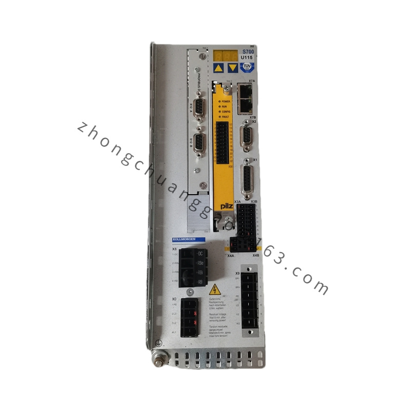
Kollmorgen PRD-0051AMPF-X0
Product Brief Introduction
This is a dedicated replacement printed circuit board core control unit for Kollmorgen legacy PRD-series analog servo amplifiers. It integrates power gate drive circuits, analog error amplifier modules, tachometer signal conditioning circuits, overcurrent thermal protection logic, and external I/O terminal interface circuits. It acts as the central signal processing core to regulate DC output current for B-series brushed servo motors, fully compatible with B-404-D series motor assemblies.
Detailed content
Technical Specifications
- Power Circuit Parameters
- Main Input AC Supply: 110/220 VAC single-phase 50/60 Hz
- Max DC Output Armature Current: 12.8 A peak, 4.3 A continuous
- Internal Bus DC Voltage: 105 VDC nominal
- Switching Frequency of Power Stage: 16 kHz
- Signal Circuit Parameters
- Command Input Signal Range: ±10 VDC analog differential voltage
- Tachometer Feedback Input Impedance: 100 kΩ differential
- Control Loop Bandwidth: 320 Hz speed loop bandwidth
- External I/O Logic Voltage: 24 VDC sink/source digital signals
- Protection Threshold Parameters
- Overcurrent Trip Threshold: 14 A instantaneous shutdown
- Over-temperature Trip Threshold: 85°C PCB surface temperature
- Under-voltage Lockout Threshold: 78 VDC internal bus
- Short-circuit fault response time: < 2 microseconds
Functional Features
- Dual-channel differential analog speed command input for noise rejection in industrial electrical environments
- Built-in active low-pass filter for tachometer feedback signal smoothing
- Adjustable proportional/integral analog gain potentiometers for loop tuning
- Hardware hardwired overcurrent, over-temperature, under-voltage fault protection with latching fault indicator LED
- External enable, fault reset, brake control digital I/O terminals
- X0 suffix configuration includes integrated regenerative braking power shunt circuit
- Galvanic isolation between high-power armature circuit and low-voltage control signal circuits
Working Principle
External ±10V analog speed command signal and motor tachometer feedback voltage feed into differential analog error amplifier on PCB. The amplifier generates deviation voltage proportional to speed error, which drives PWM gate drive circuits to adjust H-bridge power stage output DC voltage and current to the servo motor armature. On-board temperature sensors and current sampling resistors continuously monitor operating conditions; any parameter exceeding rated threshold triggers immediate power stage shutdown and latches fault state until manual reset signal is received. The X0 integrated shunt circuit dissipates regenerative energy generated during motor deceleration or reverse rotation as resistive heat.
Material Composition
- Substrate: FR4 high-temperature flame-retardant PCB, 1.6mm thickness
- Power Components: Silicon IGBT power switching transistors, fast recovery rectifier diodes
- Control Components: Precision operational amplifiers, carbon film trimming potentiometers, tantalum signal capacitors
- Connector Hardware: Gold-plated copper male/female terminal connectors with PA66 flame-retardant plastic housings
- Heat Dissipation Components: Aluminum extrusion heat sink bonded to power semiconductor devices with thermal conductive silicone pad
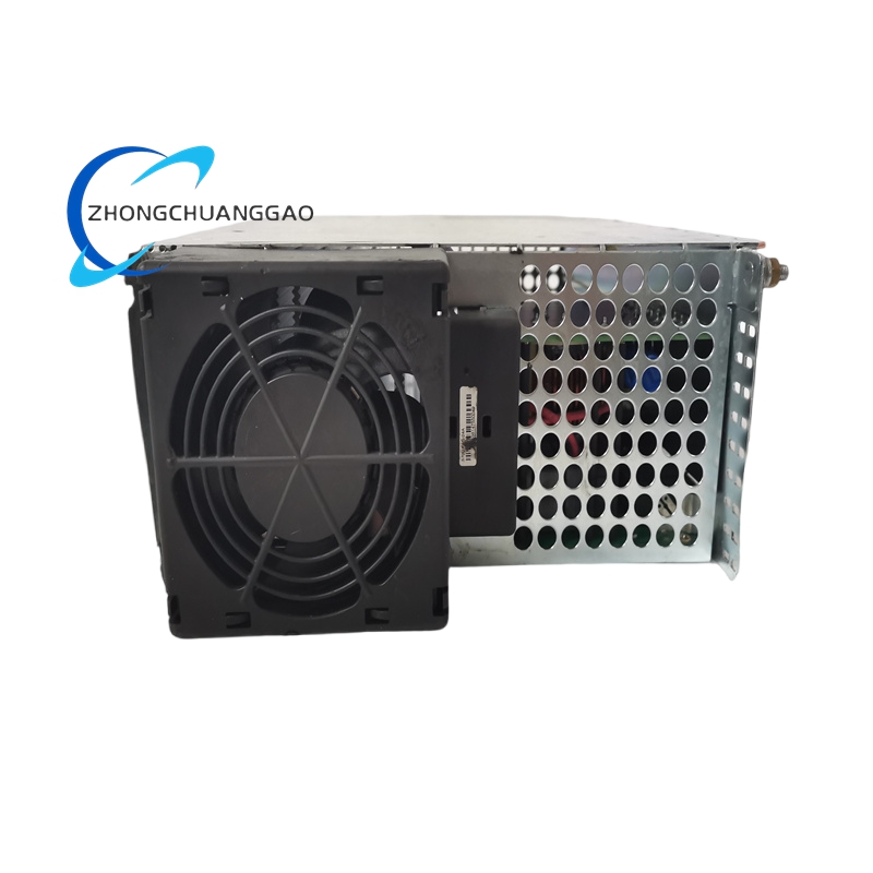
Structural Characteristics
- Standard rack-mount PCB dimension: 220mm (length) × 115mm (width)
- Zoned layout: separate power circuit zone, analog signal zone, digital I/O zone to minimize crosstalk
- Horizontal aluminum heat sink mounted along one long edge of PCB for forced air cooling
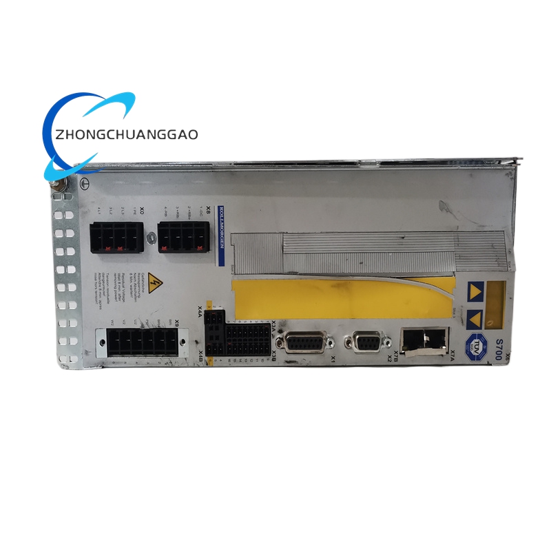
- Edge-mounted industrial screw terminal blocks for power, motor, feedback and control wiring
- Surface-mount low-profile signal components on top layer; through-hole high-current power components on bottom layer
Advantage Highlights
- Direct plug-and-play replacement for all PRD-0051 base amplifier chassis without software reconfiguration
- Integrated regenerative shunt (X0 variant) eliminates external braking resistor installation cost
- Fully analog control architecture with zero digital latency for ultra-fast low-speed response
- Hardware fault protection independent of control signal input to prevent catastrophic motor damage
- Trimmable analog loop gains to match all Kollmorgen B-frame brushed servo motor models
- Galvanic isolation eliminates ground loop signal distortion in multi-axis equipment
Applicable Industries
Vintage automated production lines, textile machinery, analog printing equipment, laboratory motion test benches, legacy machine tool servo axis retrofits, material handling low-speed positioning systems
Installation Requirements
- Install PCB only inside original PRD-series amplifier metal chassis with dedicated guide rail slots
- Ensure 10mm minimum airflow gap between PCB heat sink and chassis ventilation grille
- Torque all terminal block wiring screws to 1.8 N·m to avoid loose high-resistance connections
- Separate power wiring and signal wiring into dedicated chassis cable routing channels
- Chassis metal enclosure must connect to equipment protective earth ground with 4mm² copper wire
Operation Precautions
- Do not power on PCB outside original matched metal chassis without heat sink ventilation
- Adjust analog gain potentiometers only while motor is unloaded to prevent uncontrolled shaft runaway
- Clear regenerative shunt heat sink dust accumulation every 500 operating hours to avoid over-temperature faults
- Disconnect main AC supply before all PCB wiring modification or gain adjustment operations
- Do not apply input command signal exceeding ±12 VDC to prevent permanent analog amplifier circuit damage
- Fault latch state can only be cleared via dedicated digital reset input; power cycle alone will not release fault lockout
.jpg)
