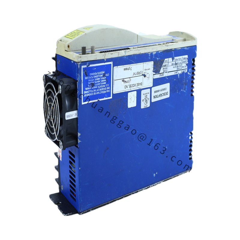
Max speed: 3000 RPM (rated) / higher transient allowed by drive
Continuous stall torque (40 °C): 17.4 Nm
Continuous stall torque (25 °C): 18.4 Nm
Peak torque: 49.5 Nm
Continuous line current: 15 A RMS
Peak line current: 45 A RMS
Torque constant: 1.15 Nm/A RMS
Back-EMF (line-to-line): 70 V RMS/kRPM
Stator resistance (L-L): 0.674 Ω
Stator inductance (L-L): 13.3 mH
Rotor inertia: 0.00775 kg·m²
Poles: 6
Holding brake: Yes (B3 suffix), 24 VDC release
Weight: approx. 20 kg
Thermal time constant: 28 min
Insulation: Class H, built-in thermostat
Functional Features:
NdFeB permanent-magnet rotor, medium inertia for stable load matching
Ribbed cast-aluminum housing, natural convection
Rear mounting face with metric or NEMA flange
Resolver or encoder feedback (062 option typically resolver + special shaft)
Material & Structure:
Stator: laminated silicon steel, 6-pole 3-phase winding, Class H varnish
Rotor: bonded NdFeB magnets on steel hub
Housing: cast aluminum with longitudinal cooling ribs
Shaft: alloy steel, keyway or plain per option
Brake: spring-applied electromagnetic disk brake
Working Principle:
3-phase stator currents produce rotating field; permanent-magnet rotor follows field angle; electronic commutator (in drive) uses resolver to align current vector at 90° electrical for max torque per amp.
Application Scenarios:
Injection-molding ejector shafts, press-feed rollers, large rotary index tables, winder/unwinder tension axes, machine-tool C-axis.
Installation Requirements:
Rigid flange mount to machined surface; shaft alignment < 0.05 mm TIR
Brake supply from isolated 24 VDC with surge protection
Feedback cable shielded, separated from power by >100 mm or metal partition
Usage Notes:
Do not disassemble rotor from stator without magnet demag risk. Brake is holding-only, not dynamic stopping. Verify A9 winding matches drive bus voltage before energizing.
.jpg "PRD-AMPE25EB-00(1)")

.jpg)