
Digital guide
You are here:
- Home
- Kollmorgen
- Kollmorgen M-403-B-B1
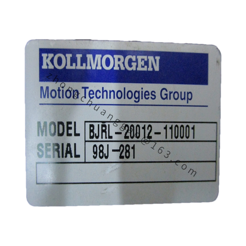
Kollmorgen M-403-B-B1
Product Overview
M-403-B-B1 is a mid-frame medium-inertia AC brushless servo motor manufactured under Kollmorgen Goldline M platform. Model breakdown: M = medium rotor inertia series classification; 403 = stator frame stack dimension code; first B = 230VAC winding voltage grade; suffix B1 = incremental resolver feedback + standard keyed output shaft mechanical configuration.
Detailed content
Technical & Performance Specifications
- Rated Input Voltage: 230 VAC Single/Three Phase
- Continuous Stall Torque: 4.7 N·m
- Peak Overload Torque: 14.1 N·m (300% rated torque, 5-second sustainable)
- Rated Continuous Operating Speed: 2500 RPM
- Maximum Mechanical Safe Speed: 5000 RPM
- Rotor Moment of Inertia: 0.00142 kg·m²
- Insulation Thermal Class: Class F (155°C maximum winding withstand temperature)
- Feedback Device: Multi-pole analog resolver (B1 suffix standard configuration)
- Output Shaft Type: Standard keyed cylindrical shaft with DIN standard keyway
- Winding Thermal Time Constant: 38 minutes
- Motor Overall Weight: 6.9 kg
- Housing Protection Rating: IP65 shaft side, IP54 rear encoder housing
Material Composition
- Stator Outer Housing: Die-cast aluminum alloy with black matte anti-corrosion anodized coating
- Rotor Lamination Core: Cold-rolled oriented silicon steel stacked core bonded with high-temperature epoxy adhesive
- Permanent Magnet: Surface-mounted NdFeB rare-earth magnet bonded to rotor outer circumference
- Bearing Assembly: Double heavy-duty sealed radial ball bearings with high-temperature lithium grease lubrication
- Resolver Feedback Stator/Rotor: High-temperature insulated copper wire wound electromagnetic resolver assembly
- Shaft Material: Medium carbon steel quenched and tempered with hard chrome plating anti-wear surface treatment
Structural Features
- Medium-inertia rotor stack design with extended lamination length for sustained constant torque output
- External machined heat dissipation fin array integrated on aluminum stator housing
- Rear-side fully isolated resolver feedback compartment physically separated from power stator windings to eliminate EMI signal interference
- Standard IEC NEMA frame mounting flange with pre-drilled bolt hole pattern for universal mechanical mounting
- Keyed output shaft design to eliminate rotational slippage under continuous high-load torque conditions
- Built-in PTC thermistor winding temperature monitoring sensor with dedicated signal wiring terminal
Working Principle
Three-phase sinusoidal vector control excitation current supplied by matched Kollmorgen servo drive generates rotating electromagnetic stator flux field. Surface-mounted NdFeB permanent magnets on medium-inertia rotor interact with stator flux to produce stable continuous rotational torque. Rear-mounted analog resolver outputs sine/cosine analog position signals proportional to rotor angular position to servo drive, forming full closed-loop velocity and position control cycles. Embedded PTC thermistor transmits winding temperature signals to drive hardware for automatic overheat load derate and fault lockout protection. Medium rotor inertia design suppresses instantaneous load fluctuation speed deviation during continuous cycle operation.
Function Features
- Medium rotor inertia delivers stable constant-speed operation under fluctuating cyclic load conditions
- Analog resolver feedback immune to industrial dust, vibration and wide temperature variation environments
- Class F high-temperature insulation enables sustained full-load operation at elevated ambient temperatures
- Keyed output shaft eliminates coupling rotational slip under peak torque overload cycles
- Integrated PTC thermal protection interlock prevents winding burnout during prolonged overload operation
- Dual-sealed bearing assembly reduces lubrication maintenance frequency to 25,000 operating hour intervals
Advantage Highlights
- Medium rotor inertia architecture minimizes speed fluctuation for continuous-cycle production equipment
- Resolver feedback offers superior long-term reliability vs optical encoders in harsh workshop environments
- Die-cast aluminum finned housing accelerates heat dissipation for extended full-load runtime
- Standardized NEMA mounting flange enables direct drop-in replacement of legacy Goldline M-series motor units
- UL, CE, RoHS certified for global industrial equipment OEM integration
Applicable Industries
Continuous web printing machinery, extrusion processing auxiliary axes, automated conveyor drive systems, metal stamping press feed axes, textile fiber spinning equipment, woodworking CNC routing machines
Installation Requirements
- All mounting orientations permitted; vertical downward shaft mounting requires rear drain plug installation to prevent moisture condensation ingress
- Mounting flange bolt specification: M8 Grade 8.8 hex socket bolts tightened to uniform 24 N·m torque with anti-loosening spring washers
- Shaft coupling radial runout tolerance limited to ≤0.04mm to prevent accelerated bearing wear
- Power motor cable and resolver feedback cable physical separation minimum 20cm; perpendicular cross routing only
- Unobstructed airflow clearance minimum 70mm surrounding motor housing heat dissipation fins
- Motor housing protective earth terminal wired to cabinet star ground grid via ≥4mm² shielded copper cable
Operation & Maintenance Precautions
- Ambient operating temperature range: -5°C ~ +40°C; temperature above 40°C apply linear 6% continuous torque derate per 10°C temperature rise
- Maximum operating altitude 1000m above sea level; elevation exceeding 1000m requires 6% torque derate per 1000m increase
- Ambient relative humidity ≤85% non-condensing; prohibit deployment in corrosive gas or conductive dust atmospheres
- Avoid direct radial impact loading on output shaft during mechanical coupling installation
- Conduct bearing grease replenishment every 25,000 continuous operating hours via rear grease fitting port
- Cut all servo drive mains power supply before disconnecting resolver or motor power connectors to eliminate electrostatic discharge damage to resolver windings
