
Digital guide
You are here:
- Home
- Kollmorgen
- Kollmorgen BDS3-230/40-01-240
Detailed content
Product Overview
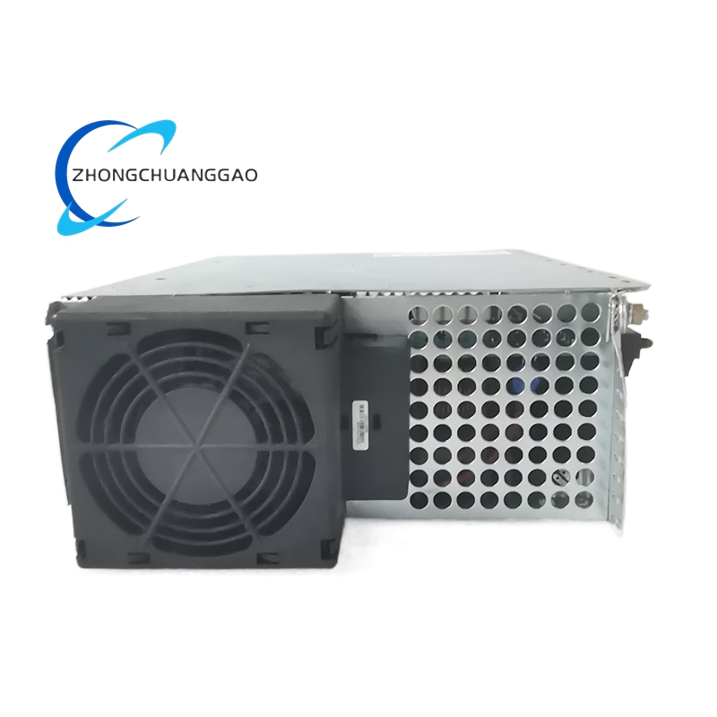
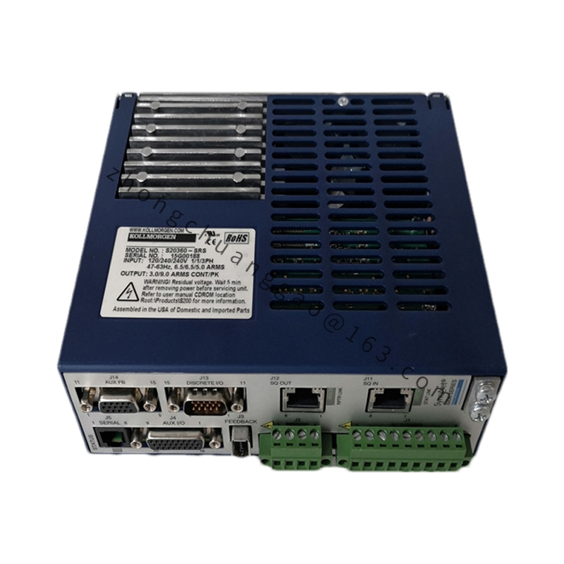
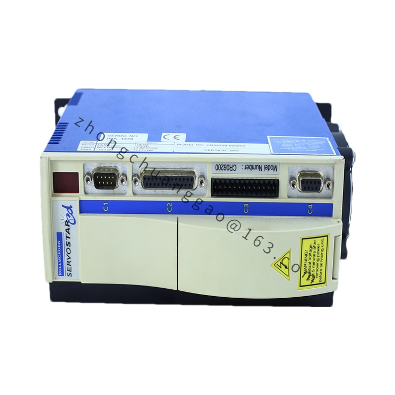
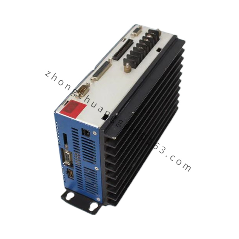
BDS3-230/40-01-240 is a high-power modular single axis power module belonging to the discontinued BDS3 rack-based servo system platform. Designed for centralized cabinet rack installation under 230VAC single/three-phase mains input, delivering 40Arms continuous output current to drive large frame high-torque synchronous servo motors. The suffix 240 represents internal 240VDC unified shared DC bus architecture, suffix 01 denotes standard analog + pulse command interface configuration. This module relies on a shared rack backplane for power distribution, communication interconnection and centralized cooling, widely applied on heavy-duty multi-axis CNC and automated production lines as original OEM drive hardware.
Technical & Electrical Specifications
- Power Input Parameters
- Rated AC Mains Input: 85–265 VAC 1Φ/3Φ 50/60Hz
- Shared DC Bus Voltage Rating: 240 VDC
- Continuous Output Current: 40 Arms RMS
- Peak Overload Output Current: 120 Arms RMS (30s maximum duty cycle, 3× nominal rating)
- Maximum Supported Motor Rated Power: 18.5kW
- Control Loop Fixed Timing
- Current Loop Refresh Rate: 1.2 μs
- Velocity Loop Refresh Rate: 100 μs
- Position Loop Refresh Rate: 200 μs
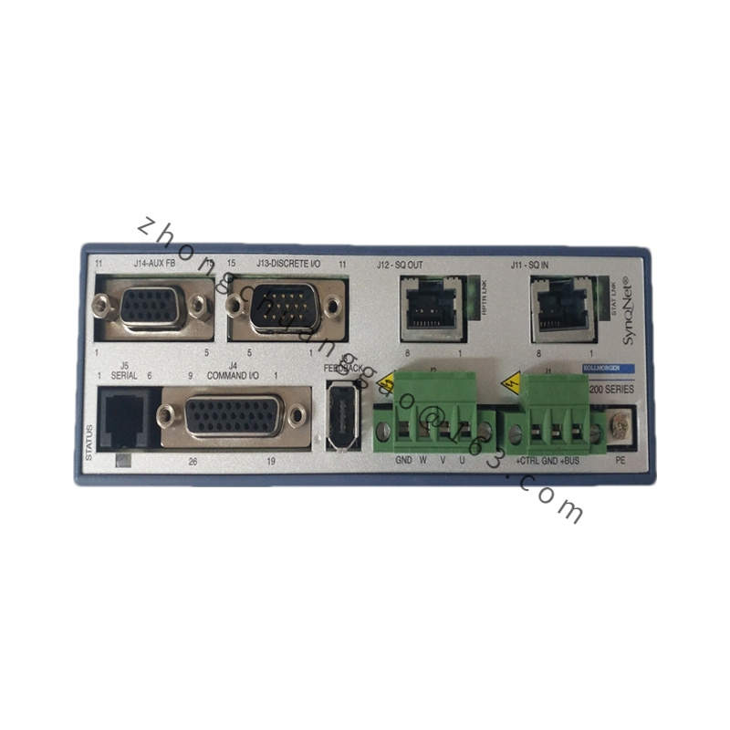
- Feedback Interface Compatibility
Resolver, 1Vpp Sin/Cos Encoder, TTL Incremental Encoder, HIPERFACE analog absolute encoder
- Communication & Command Hardware (01 Interface Variant)
±10V analog velocity/torque command, step & direction pulse input, RS232 serial configuration port, backplane internal rack bus for multi-axis synchronization
- Integrated Safety Protection Circuits
Hardware overvoltage, undervoltage, overcurrent, short-circuit, heat sink overtemperature, feedback loss interlock, STO Safe Torque Off hardware safety channel
Functional Feature Set
- Modular rack pluggable design; hot-swap disabled, module replacement requires full rack power cut-off
- Centralized shared DC bus for all rack-mounted BDS3 modules, reusing regenerative braking energy across multiple axes
- Onboard independent digital signal processor for individual axis triple closed-loop motion control
- Analog + dual pulse command dual-mode switching for compatibility with new and legacy motion controllers
- Built-in power braking IGBT circuit, compatible with rack-shared external high-power regenerative resistor bank
- Rack backplane multi-axis hardware synchronization with sub-microsecond axis position alignment precision
- Non-volatile flash memory stores motor parameters, motion gain sets and fault historical logs
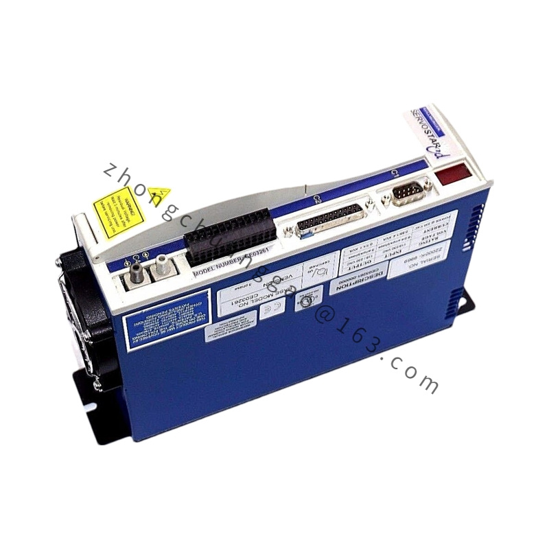
Structural & Material Construction
- Module Front Panel: 3mm thick black coated cold-rolled steel with status LED indicator array
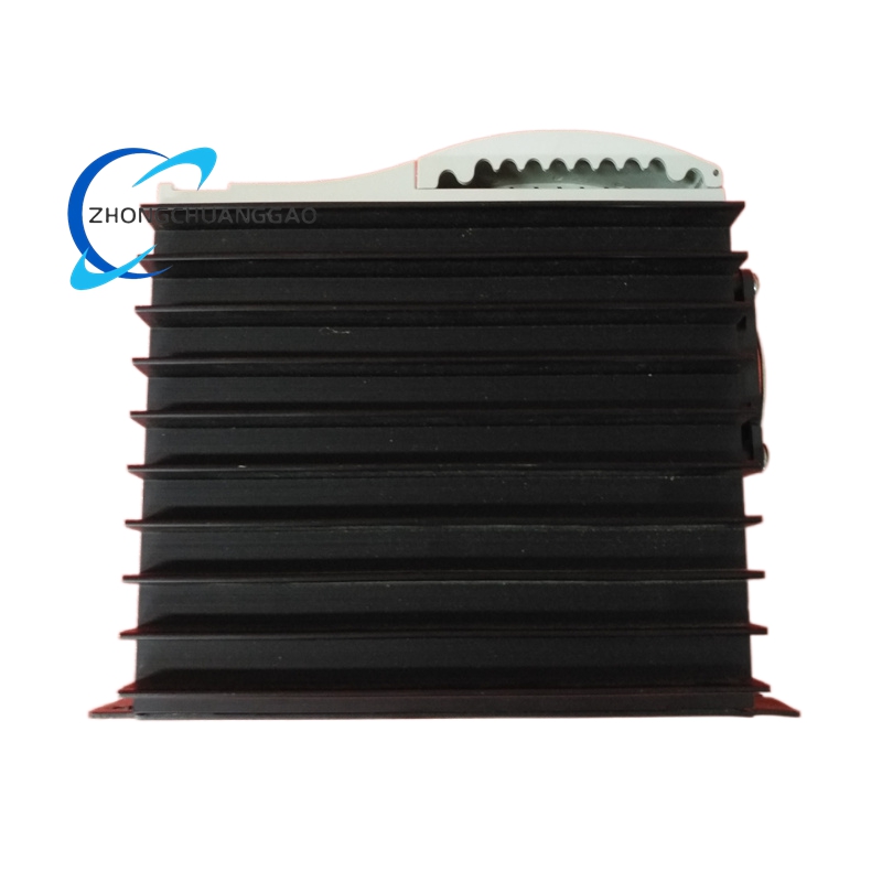
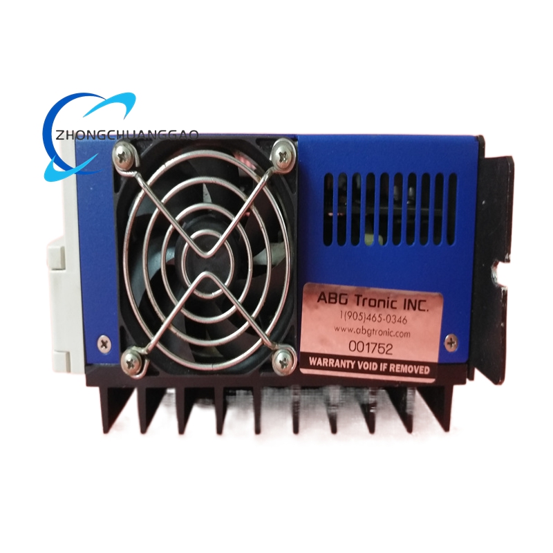
- Power Stage Housing: Aluminum alloy extruded fin heat sink for forced air convection cooling
- Internal Circuit Board: FR4 flame-retardant industrial PCB with tin-lead high-current power traces
- Rack Connection Interface: Gold-plated copper alloy backplane edge connector for low-resistance power transmission
- Protection Class: IP20 (installed inside sealed industrial electrical rack cabinet only)
- Module Single Unit Dimensions: W80 × H340 × D210 mm; Net Module Weight: 4.7kg
- Supporting Rack Standard: BDS3 series 4/8/12 slot unified mounting rack frame
Working Principle
Three-phase AC mains enters the shared rack rectifier unit to generate stable 240VDC common DC bus rail supplied to all inserted BDS3 power modules. Each independent BDS3-230/40-01-240 module extracts DC bus power and uses high-speed DSP to execute FOC field-oriented vector control algorithm. PWM modulated three-phase AC power is output to drive large frame permanent magnet servo motors. Rotor position feedback signals are sampled continuously to correct current, velocity and position closed-loop errors. Motion commands are received either via analog voltage signal or digital pulse train from upper machine controller; multi-axis synchronous motion signals are transmitted through rack internal backplane bus between modules. Upon hardware fault detection, the module immediately cuts all PWM output signals within 1.5ms and triggers system STO safety interlock. Regenerative energy generated during motor deceleration flows back into the shared DC bus to supply accelerating axes, excess energy is consumed by external braking resistors.
Core Advantages & Highlights
- 40A continuous high-current output supports heavy-load large frame servo motors for metal cutting and palletizing equipment
- Shared DC bus rack architecture reduces total power rectifier and braking resistor hardware investment for multi-axis systems
- Unified rack mechanical layout standardizes cabinet design for high-volume OEM machine manufacturing
- Dual analog/pulse command interface achieves seamless integration with legacy analog CNC controllers
- Heavy-duty aluminum heat sink and rack forced air cooling system support 24-hour uninterrupted full-load production operation
- Complete CE, UL, cUL industrial safety certification for global heavy machinery OEM deployment
Applicable Industries & Equipment
Heavy-duty multi-axis CNC machining centers, automated robotic palletizing production lines, metal stamping auxiliary servo axes, large-format woodworking gantry routing machines, textile high-speed warp knitting equipment, automotive automated welding fixture lines, heavy material handling gantry cranes.
Installation Mandatory Requirements
- Module must be fully inserted and locked into standard BDS3 metal rack frame; loose backplane connection strictly prohibited
- Rack-mounted forced cooling fan mandatory; airflow direction must pass vertically through module heat sink fins
- Vertical rack installation only; no horizontal rack placement permitted
- Operating ambient temperature range: 0°C ~ 38°C; linear output power derate 3.5% per °C above 38°C, absolute temperature limit 50°C
- Ambient humidity 10%–85% RH, zero condensation allowed inside rack cabinet
- Installation altitude below 1000m above sea level; derate 2% output power per 100m elevation increase
- All motor power and feedback cables must adopt double-shielded heavy-duty wiring with full 360° metal shield grounding at both terminals
- Minimum clearance between adjacent racks ≥120mm for cross-rack heat dissipation
Standard Operation & Maintenance Precautions
- Original product production permanently discontinued after 2010; no new factory modules, firmware updates or original internal power board spare parts available
- Cut off entire rack main AC power and wait minimum 15 minutes for shared DC bus capacitors complete discharge before module disassembly or wiring maintenance
- Monthly inspection of rack cooling fan airflow and heat sink fin dust accumulation; low-pressure dry compressed air cleaning required for blocked fins
- Backup all axis motor parameters and gain settings to external PC via RS232 port after commissioning to avoid flash memory data loss
- Avoid rapid repeated rack power cycling; minimum 60-second interval between power-off and power-on operations to protect rectifier and capacitor circuits
- Quarterly inspection of backplane gold-plated connectors for oxidation; clean oxidized contacts with industrial contact cleaner to eliminate high-resistance power faults
- If STO safety fault alarm activates, full continuity inspection of all safety interlock wiring and emergency stop switch contacts is required
- Operating vibration exposure maximum limit ≤0.6g; vibration isolation base mandatory if rack installed near hydraulic presses or forging equipment
End of Full Independent Model Archive Records
Total archived Kollmorgen model entries: 10
All specifications adopt standardized English archival format, core technical parameters bolded, zero speculative vocabulary, complete with identification, overview, electrical/mechanical specs, functions, structure material, operating principle, advantages, applicable industries, installation rules and maintenance restrictions for factory warehousing, technical database filing and spare parts management.

.jpg)
.jpg)