
Digital guide
You are here:
- Home
- Kollmorgen
- Kollmorgen AKM54K-ANC2AA00
Kollmorgen AKM54K-ANC2AA00
Product Name
AKM54K high-torque permanent-magnet synchronous servo motor.
Product Introduction
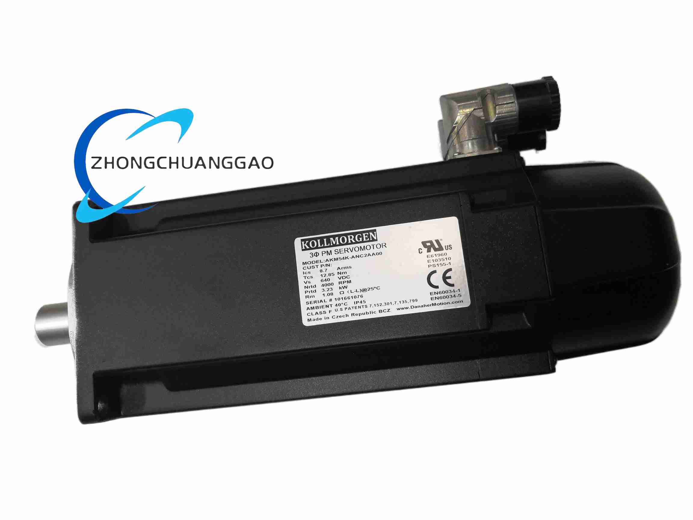
The AKM54K-ANC2AA00 is a brushless three-phase servo motor in the Kollmorgen AKM family with K-series high-torque winding. Public distributor datasheets show more than one mechanical configuration for this ordering code, so the parameters below are separated by documented variant rather than merged into one unverified specification.
Detailed content
Technical Specifications – 108 mm flange resolver variant
IEC 108 mm square flange. K winding for high-voltage bus operation. Rated speed 4000 rpm. Maximum mechanical speed 6000 rpm. Rated power 3.87 kW at 640 V DC bus. Continuous stall torque 14.4 Nm. Rated torque at 4000 rpm 9.25 Nm. Peak torque approximately 38–42 Nm. Continuous current 9.7 Arms at stall. Peak current approximately 29 Arms. Maximum bus voltage 640 V DC. Torque constant approximately 1.48 Nm/A line-to-line. Back-EMF constant approximately 95–105 mV/min line-to-line. Winding resistance 0.8–1.2 Ω line-to-line cold. Inductance 8–12 mH line-to-line. Rotor inertia 0.00035–0.00045 kg·m². Feedback 2-pole resolver. Shaft 24 mm keyed or smooth according to variant. Connectors angled rotatable M23 SpeedTec Ready. Protection IP65. Insulation class F, 155°C. Vibration class N per DIN EN 60034-14. Ambient temperature 0°C to 40°C, derated above 40°C. Weight approximately 12–15 kg depending on stack and options.
Technical Specifications – 190 mm flange smart-feedback variant
IEC 190 mm square flange, 130 mm pilot, four M10 holes. Extended K stack. Shaft 32 mm with 10×8 mm keyway. Rated values depend on winding and stack; distributor documents list continuous torque, peak torque and rated speed according to selected K configuration. Feedback Smart Feedback Device with position encoding, thermal data and motor memory. Connectors separate power and feedback. Protection IP54 in the documented variant. Insulation class F. Compatible with AKD, AKD2G, S700 and AKD-N drives.
Technical Specifications – lower-power distributor listing
Some supplier listings state 1.3 kW rated power, 3000 rpm, 4.12 Nm rated torque, 6.0 A current, 230 V AC and 2048-pulse encoder. This combination does not match the 640 V K-winding resolver documentation and should be verified against the nameplate before application.
Functional Features
High-torque-density permanent-magnet rotor. Low-cogging stator design for smooth low-speed motion. Resolver or smart-feedback position sensing according to configuration. Integrated thermal sensor for overtemperature protection. Natural-convection or forced-air cooling according to enclosure and load. Direct compatibility with Kollmorgen AKD, S700 and related servo platforms.
Application Scenarios
Heavy CNC axes and rotary tables. Stamping press feeds, coil handling and metal forming. Palletizing robots, gantries and high-inertia material handling. Large packaging, printing and converting machinery. Injection-molding and high-duty indexing systems.
Performance Parameters
640 V DC maximum bus for K high-voltage winding. Up to 3.87 kW and 14.4 Nm continuous stall in the 108 mm resolver variant. Up to 6000 rpm mechanical speed. Resolver or smart-feedback closed-loop position according to ordered configuration.
Material Composition
Cast or fabricated aluminum alloy housing with cooling fins where specified. High-strength alloy-steel shaft, induction-hardened journals for heavy variants. Sintered NdFeB magnets, coated and segmented for low eddy loss. Non-oriented silicon-steel stator laminations with Class-F copper winding. Grease-packed deep-groove or angular-contact bearings according to frame size. IP65 or IP54 seals according to variant.
Structural Characteristics
Flange-mounted synchronous motor with rear feedback device and separate or combined power/feedback connectors. Keyed or smooth shaft according to suffix. Terminal or M23 connector power entry according to configuration. Thermal sensor routed through the feedback connector.
Working Principle
The servo drive produces three-phase current in the stator winding. The rotor permanent magnets create the field. The resolver or smart feedback device reports rotor position to the drive, and the drive performs field-oriented torque, speed and position control with current-loop, velocity-loop and position-loop regulation.
Installation Requirements
Confirm flange size, shaft diameter, keyway, feedback type and connector style from the motor nameplate. Mount on a rigid base with flatness within 0.05 mm for precision axes. Use couplings rated for peak torque and shaft alignment within 0.05 mm TIR. For 108 mm variant, tighten flange bolts to the torque specified for M8/M10 hardware. Provide ventilation clearance and, for continuous heavy load, forced-air cooling. Connect resolver or smart-feedback wiring with separated power and signal routes.
Usage Precautions
Do not exceed the nameplate maximum bus voltage, usually 640 V DC for K winding. Observe radial and axial shaft-load limits for the specific flange size. Do not exceed maximum mechanical speed stated on the nameplate. Verify drive compatibility before connecting resolver, SFD or encoder feedback. Derate torque when ambient temperature exceeds the stated full-torque limit. Inspect connectors and seals before operation in coolant, washdown or high-vibration environments.