
Digital guide
You are here:
- Home
- Kollmorgen
- Kollmorgen AKD-M00306-M1E
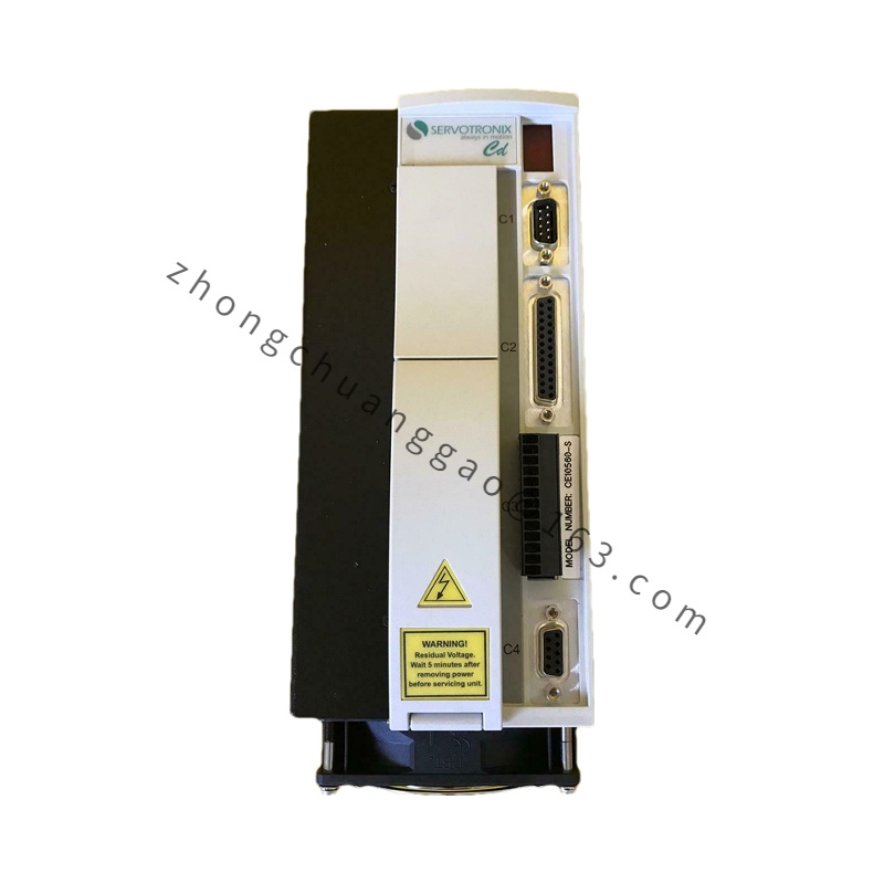
Kollmorgen AKD-M00306-M1E
Product Brief
All-in-one programmable servo amplifier integrating digital motion controller, power stage, fieldbus interface and multi-axis coordination logic; eliminates external standalone PLC for single/multi-axis automation systems, native plug-and-play matching with Kollmorgen AKM, DDR, DDL linear & rotary servo motors.
Detailed content
Technical & Performance Specifications
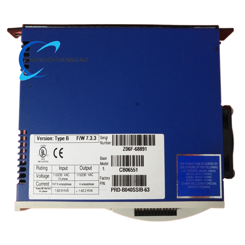
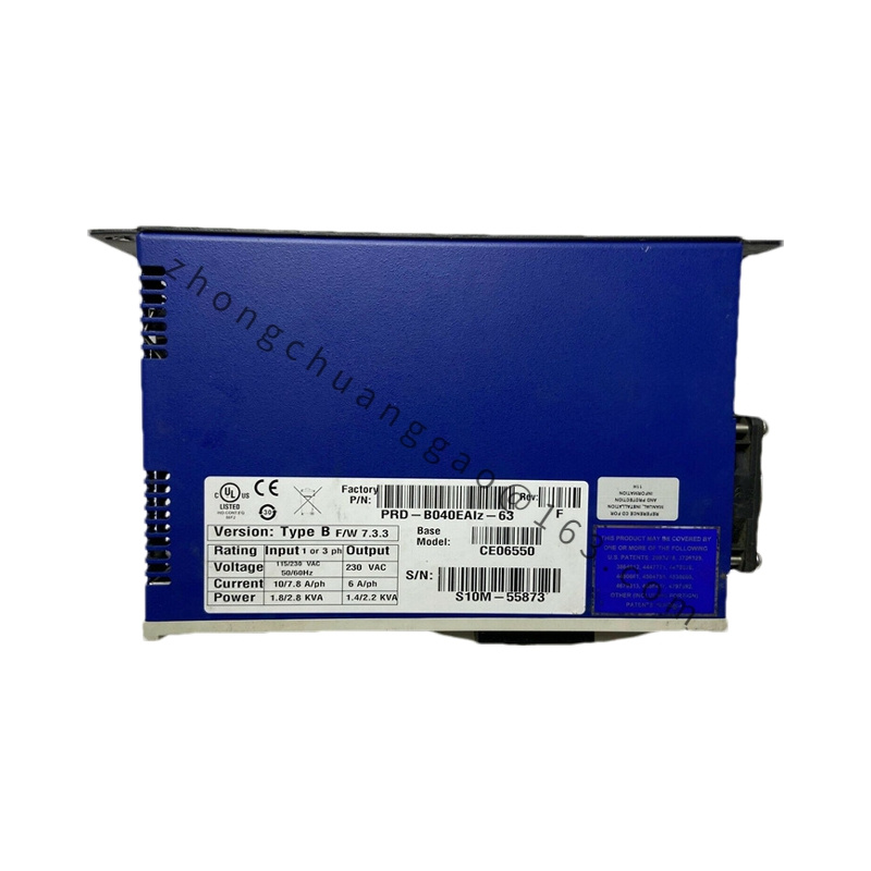
- Input Power Rating: 120/240 VAC, Single-phase / Three-phase universal input, input voltage range 85–265 VAC
- Continuous Output Current: 3 Arms
- Peak Output Current: 9 Arms
- Continuous Output Power: 1100 W
- Control Loop Refresh Rate: Torque loop = 0.67 μs, Velocity loop = 62.5 μs, Position loop = 125 μs
- Physical Dimensions: H=168 mm (6.61 in), W=89 mm (3.50 in), D=156 mm (6.14 in)
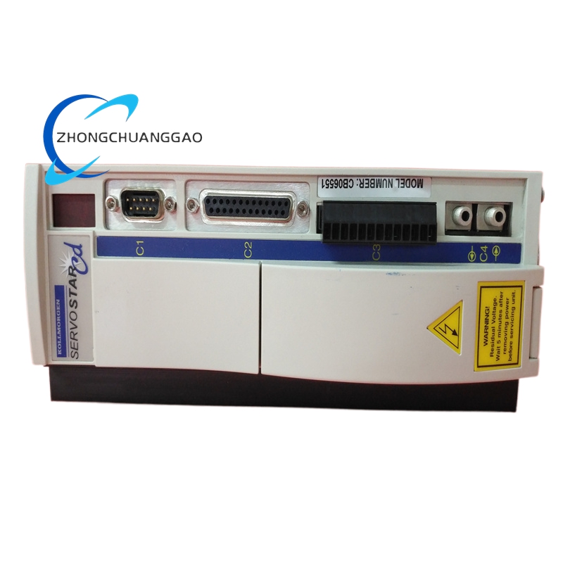
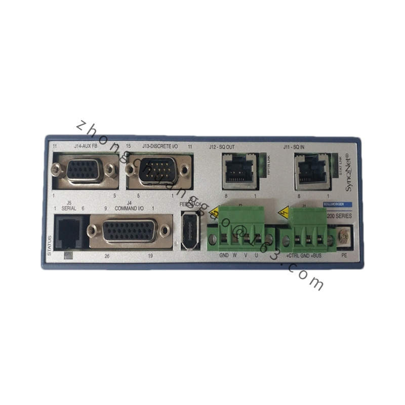
- Feedback Interface Compatibility: SFD Smart Feedback, EnDat 2.2/01, BiSS, Sine/Cos Analog Encoder, Incremental Encoder, HIPERFACE, Resolver
- Standard Fieldbus: M1E hardware variant supports EtherCAT real-time industrial Ethernet
- Safety Function: Integrated STO (Safe Torque Off) safety circuit, SIL2 certified
- Operating Ambient Temp: 0°C ~ +45°C (full rated output); derate 6% per 1000 m altitude above sea level
- Storage Temperature: -40°C ~ +85°C
- Protection Class: IP20 (cabinet internal installation only)
- Certifications: UL, cURus, CE
Functional Features
- Embedded IEC 61131-3 programming runtime via Pipe Network™ multi-axis synchronization architecture
- Built-in 16-channel digital 24VDC I/O, expandable via CEX extension bus
- Auto motor identification & one-click auto-tuning algorithm for all Kollmorgen servo motors
- Real-time multi-axis electronic cam, electronic gear, position synchronization without external controller
- Full fault diagnosis module with overcurrent, overvoltage, overtemperature, feedback loss, short-circuit alarm log storage
- Firmware upgradable via USB/EtherCAT without hardware disassembly
- WorkBench PC graphical configuration software compatible for parameter editing, oscilloscope monitoring, motion programming
Material Composition
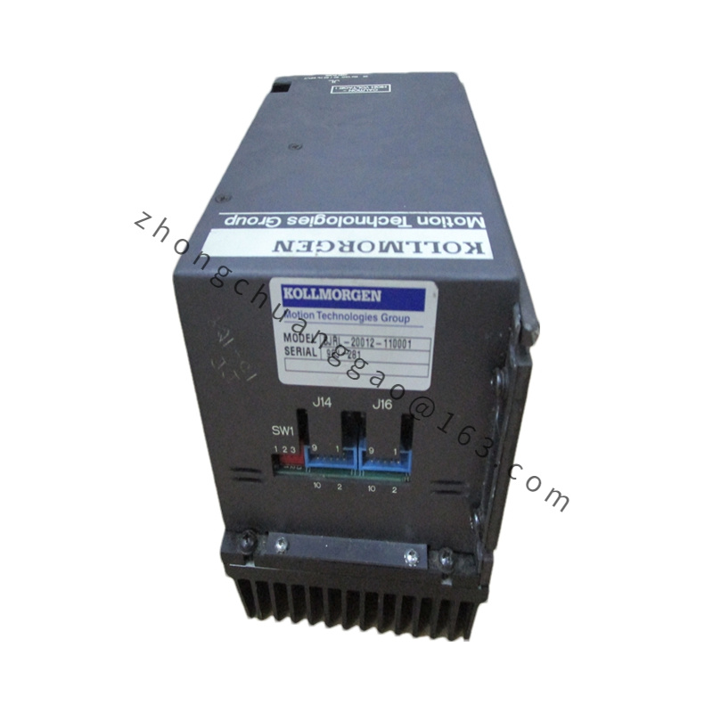
- Main housing: Cold-rolled steel sheet with black electrostatic anti-corrosion coating
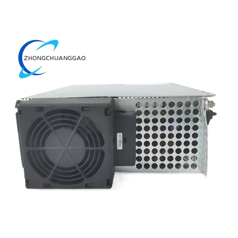
- Power heat sink: Extruded aluminum alloy with fin structure for passive heat dissipation
- Internal power module: Silicon IGBT power transistor with insulated ceramic substrate
- Terminal blocks: Reinforced flame-retardant PA66 plastic with copper conductive terminals
- PCB substrate: FR4 high-temperature flame-retardant circuit board
Structural Characteristics
- Vertical DIN rail mounting structure, single-unit compact cabinet layout design
- Separate compartment layout for power circuit, control signal circuit and bus communication circuit to eliminate electromagnetic interference
- Top ventilation fin heat sink, bottom air intake convection cooling channel
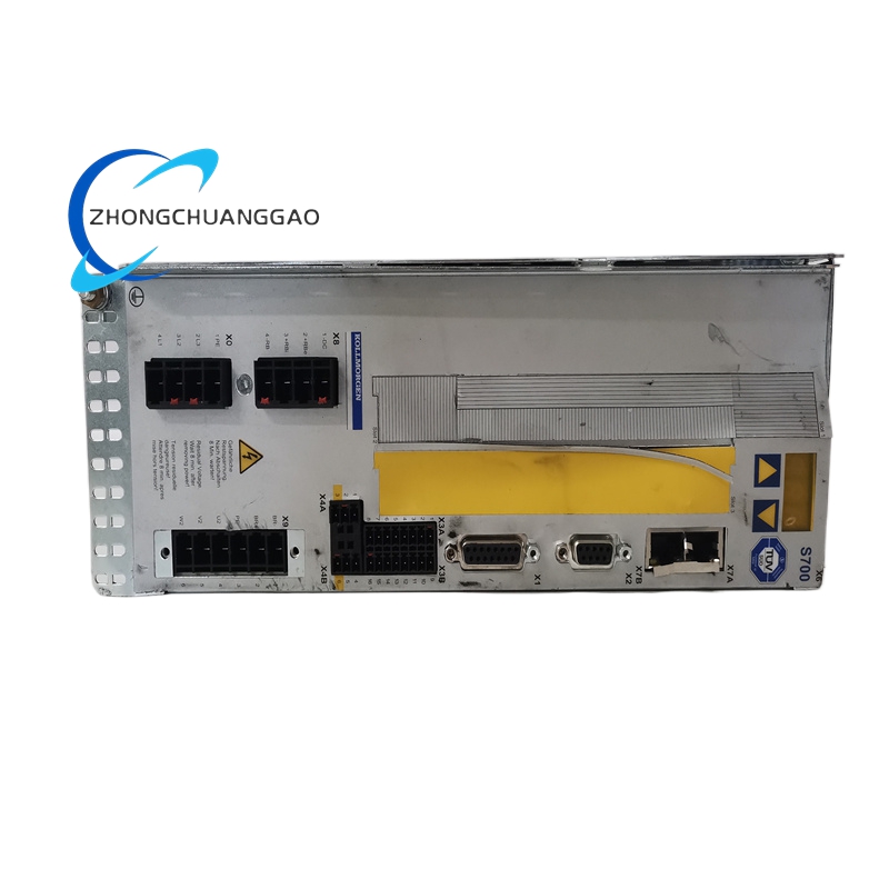
- Front-panel accessible USB debug port, status LED indicators (power, fault, bus communication, axis running)
- Rear side standardized ModuleBus multi-drive parallel connection port for multi-axis expansion
Working Principle
- AC mains input converts to regulated DC bus voltage via internal rectifier circuit
- DSP digital motion controller executes position/velocity/torque closed-loop algorithms, outputs PWM modulation signals to IGBT power stage
- Drive outputs three-phase sinusoidal current to servo motor stator windings
- Motor feedback sensor transmits real-time rotor position/velocity data back to drive feedback interface, forming full closed-loop control
- PDMM embedded motion logic directly processes host motion commands via EtherCAT bus, distributes synchronized motion instructions to local axis and cascaded slave drives through ModuleBus without intermediate PLC forwarding
Advantage Highlights
- Integrated drive + motion controller architecture reduces cabinet wiring quantity by 40% and eliminates separate PLC hardware cost
- Ultra-fast control loop refresh rate delivers sub-arc-second positioning accuracy and millisecond dynamic response
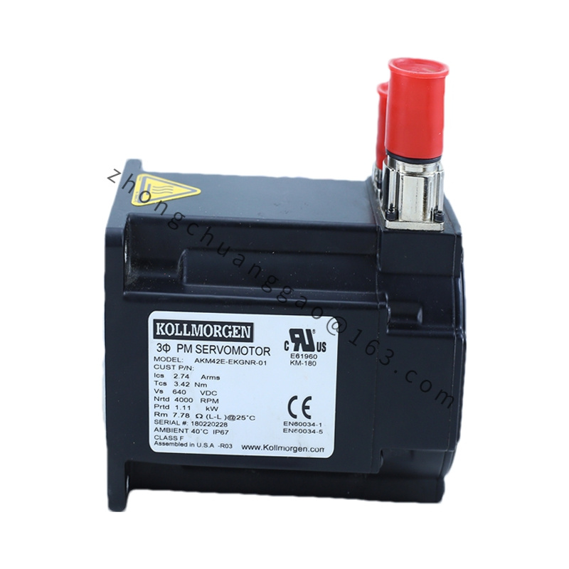
- Universal motor compatibility covers all Kollmorgen rotary, linear, direct-drive servo products
- Multi-axis synchronization precision ≤ 1 μs, ideal for high-speed synchronous production lines
- Compact power density minimizes cabinet footprint compared to split drive-controller solutions
- Built-in safety STO function meets international machinery safety standards without external safety relay
Applicable Industries
Semiconductor wafer processing equipment, precision printing machinery, pharmaceutical packaging automation, electronic assembly robots, textile high-speed winding equipment, laboratory precision positioning stages, medical diagnostic automation equipment
Installation Requirements
- Mount vertically on standard 35 mm DIN rail inside sealed industrial control cabinet
- Maintain minimum clearance: 50 mm top ventilation gap, 30 mm bottom ventilation gap, 20 mm side gap between adjacent drives
- Cabinet internal cooling fan required for continuous full-load operation above 35°C ambient temperature
- All power and signal cables must use shielded twisted pair, shield grounding at cabinet ground bar single-point connection
- Separate power cable wiring channel and signal cable wiring channel to avoid electromagnetic cross-interference
- ModuleBus multi-axis connection cable must use original Kollmorgen shielded bus cable
Usage Precautions
- Prohibit operation without cabinet enclosure; external dust, moisture and conductive debris will cause short-circuit damage
- Input AC voltage must strictly stay within 85–265 VAC; overvoltage will permanently damage internal rectifier modules
- Complete motor parameter auto-tuning before formal load operation; mismatched motor parameters trigger unstable torque output and overcurrent faults
- STO safety circuit wiring must follow official schematic; bypassing STO function voids product safety certification
- Firmware upgrade must not cut off power supply during transmission; power interruption leads to drive firmware corruption
- Regularly clean heat sink fin dust accumulation every 3 months in high-dust industrial environments to prevent overtemperature protection trigger