Digital guide

You are here:

Kollmorgen 5AF-1300-05

Product Introduction:
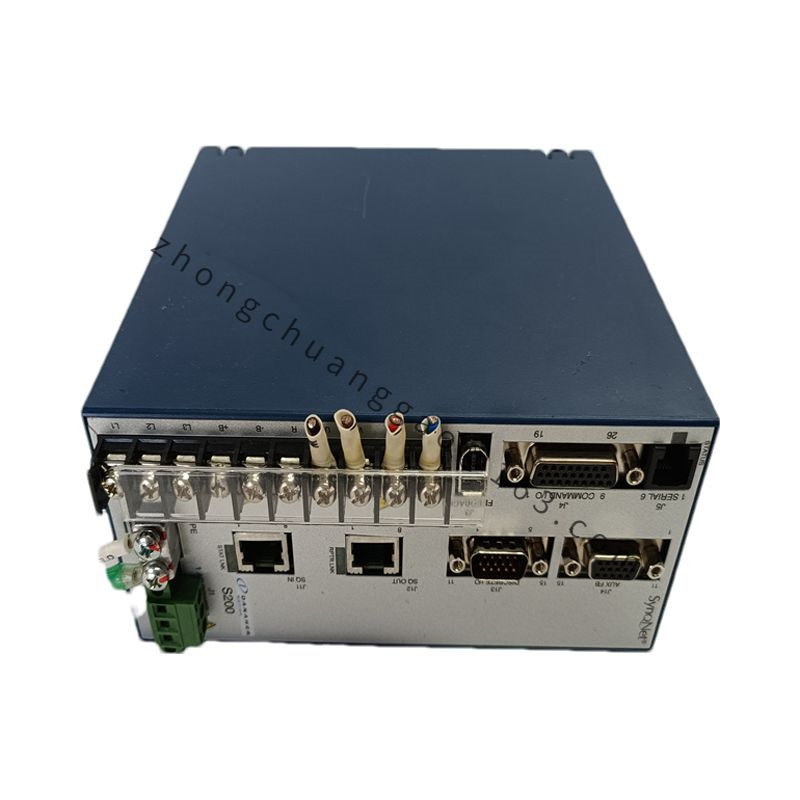
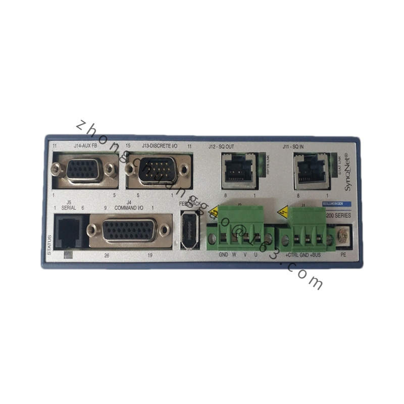
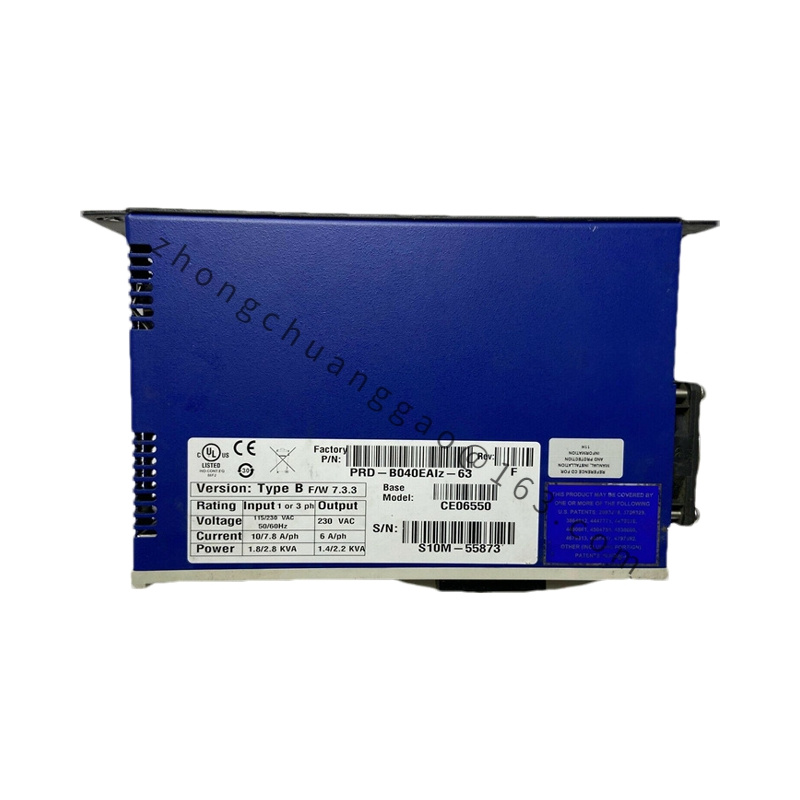
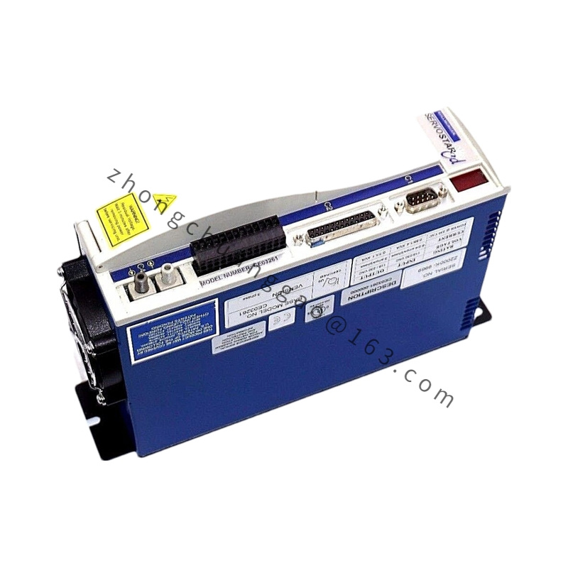
The 5AF-1300-05 is a single-phase AC line-side EMI filter designed to suppress conducted electromagnetic interference on the power input of Kollmorgen servo drives and motion controllers. It ensures compliance with EN 61800-3 / CISPR 11 electromagnetic compatibility standards and protects both the drive and upstream power infrastructure from high-frequency noise generated by PWM switching.

Detailed content

Technical Specifications:

Parameter Value
Rated Current 13 A (Continuous)
Rated Voltage 250 VAC (Single Phase)
Frequency Range 50/60 Hz
Insertion Loss >40 dB at 150 kHz – 30 MHz
Leakage Current <3.5 mA (at 250 VAC, 50 Hz)
Impedance 50 Ω / 50 Ω (Differential / Common Mode)
Capacitance (Line-Ground) <1 μF (Y-class safety capacitor)
Operating Temperature -25°C to +70°C
Mounting DIN Rail / Chassis Mount
Enclosure Rating IP20 (when properly enclosed)
Standards Compliance UL 1283, EN 60939, CISPR 11 Class A

Functional Features:

  • Dual-stage filtering: Common-mode choke + differential-mode capacitors
  • Y-class safety capacitors for line-to-ground filtering with fail-safe design
  • X-class capacitors for line-to-line differential noise suppression
  • Toroidal core inductors for high impedance at switching frequencies

Structural Features:

  • Core Material: Manganese-Zinc (MnZn) ferrite toroids
  • Capacitors: Metallized polypropylene film (X-class), Ceramic (Y-class)
  • Housing: UL94 V-0 rated flame-retardant thermoplastic
  • Terminals: Screw terminals rated for 16 AWG wire

Advantages:

  • Reduces conducted EMI by >40 dB in the 150 kHz – 30 MHz band
  • Protects drive input stage from voltage transients and noise
  • UL Listed and CE Marked for global deployment
  • Compact DIN-rail form factor saves panel space

Applicable Industries:

  • Industrial Automation
  • CNC Machining Centers
  • Packaging Machinery
  • Printing & Converting Equipment
  • Any Kollmorgen drive installation requiring EMC compliance

Installation Requirements:

  • Install between mains supply and servo drive input terminals (L1, L2, L3)
  • Ground the filter chassis to protective earth (PE)
  • Maintain minimum 50 mm clearance from heat-generating components
  • Use shielded cable from filter output to drive input

Usage Notes:

  • Do not bypass the filter under any circumstances when operating in EMC-regulated environments
  • Replace filter if leakage current exceeds 3.5 mA during routine testing
  • Verify filter rating matches or exceeds drive input current

You may also like