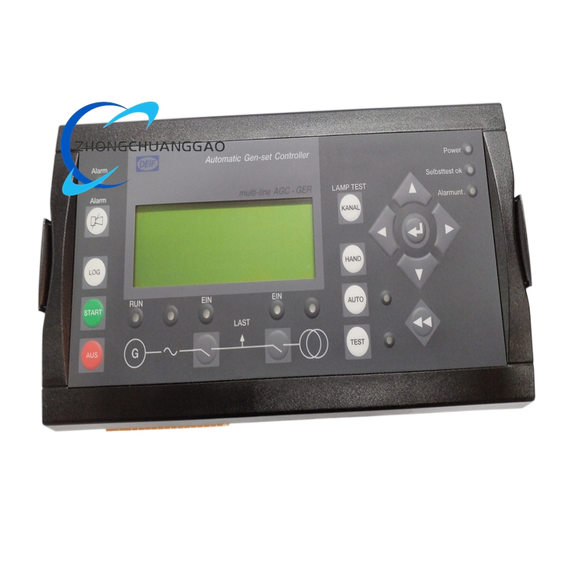
DEIF AGC/GS/3
Product Name
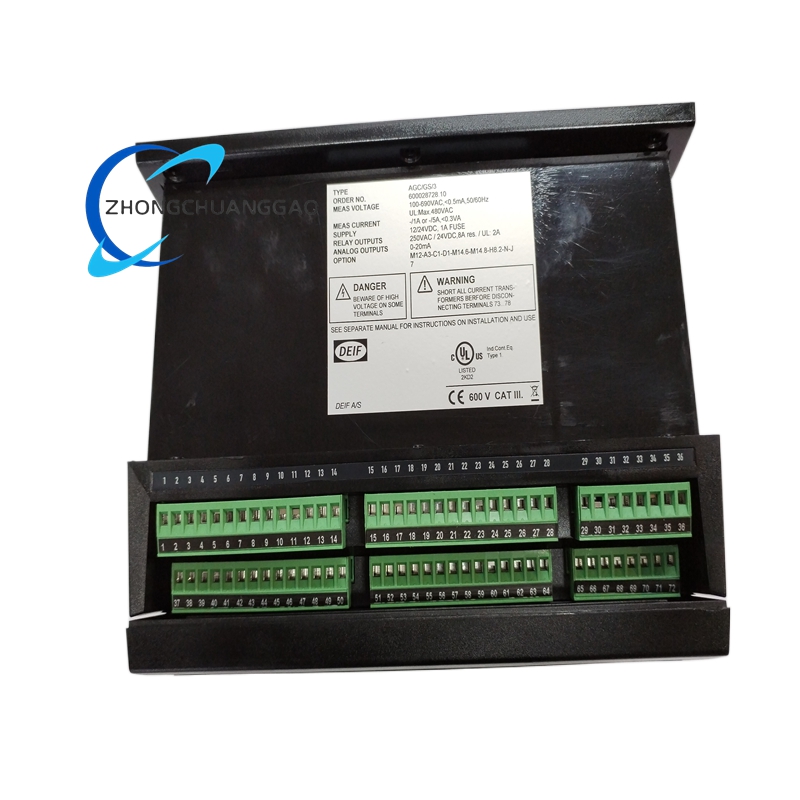
DEIF AGC/GS/3 automatic genset controller
Product Introduction
The DEIF AGC/GS/3 is an automatic genset control module used for generator monitoring, automatic start and stop, synchronizing, load sharing, and multi-unit power management. It is intended for diesel generator sets operating in island mode, parallel operation, or standby power applications.
Detailed content
Technical Specifications
- Voltage measurement: 100–690 V AC, 50/60 Hz
- Current measurement: 1 A or 5 A transformer input
- Supply voltage: 12/24 V DC
- Relay outputs: 250 V AC / 24 V DC, 8 A resistive
- Analog outputs: 0–20 mA
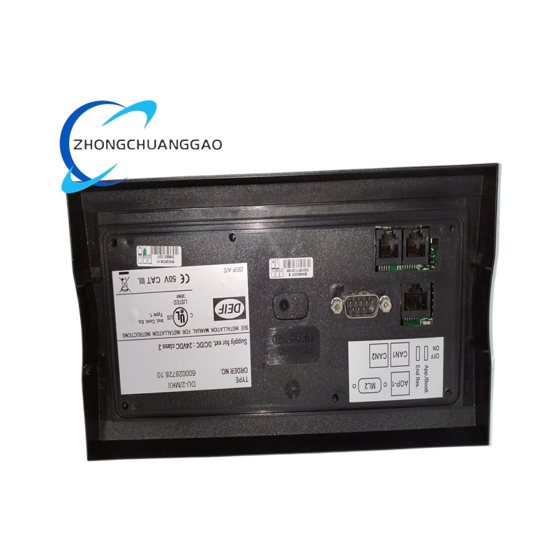
- Communication: Modbus RTU, CANopen
- Operating temperature: -25 to +70 °C
- Weight: approximately 1.52 kg
Function Features
- Automatic genset start and stop
- Voltage, frequency, phase angle, and synchronism monitoring
- Active and reactive load sharing
- Multi-unit or group control
- Configurable alarms and protection functions
- Process monitoring and operator interface through front panel or software
Application Scenarios
- Industrial standby power systems
- Hospital and data-center emergency power supplies
- Marine auxiliary power systems
- Offshore platforms
- Multi-generator islands and microgrids
- Mining and remote power stations
Performance Parameters
- Measurement accuracy suitable for generator protection and synchronization
- Fast response to voltage, current, frequency, and power changes
- Stable operation during continuous generator duty
- Supports load distribution across several generator sets
Material Composition
- Industrial-grade printed circuit board
- Metal and flame-retardant enclosure
- Electromechanical relays
- Screw terminals
- Connectors and display assembly
Structural Features
- Modular genset controller
- Panel or cabinet-mounted construction
- Front connection terminals
- Integrated display and control interface
- Compatible option modules for expanded functionality
Working Principle
The controller continuously measures generator voltage, current, frequency, and phase angle. It calculates power, compares operating parameters with configured setpoints, and sends commands to the engine governor, voltage regulator, and circuit breaker. During parallel operation, it adjusts generator speed and excitation until the incoming machine matches the bus or grid before closing the breaker.
Installation Requirements
- Install in a clean, dry control cabinet
- Maintain adequate clearance for ventilation and wiring
- Use correctly rated control and voltage transformers
- Tighten terminals to the torque specified in the installation manual
- Keep low-level measurement wiring away from high-current conductors
- Verify generator, CT, VT, and protection settings before energizing
Usage Precautions
- Do not remove or replace the module while the generator is running.
- Confirm system voltage, CT ratio, and wiring before commissioning.
- Verify synchronization and load-sharing parameters under controlled conditions.
- Backup configuration data before firmware or module replacement.
- Only use option codes approved for the installed hardware revision.