Supply Voltage
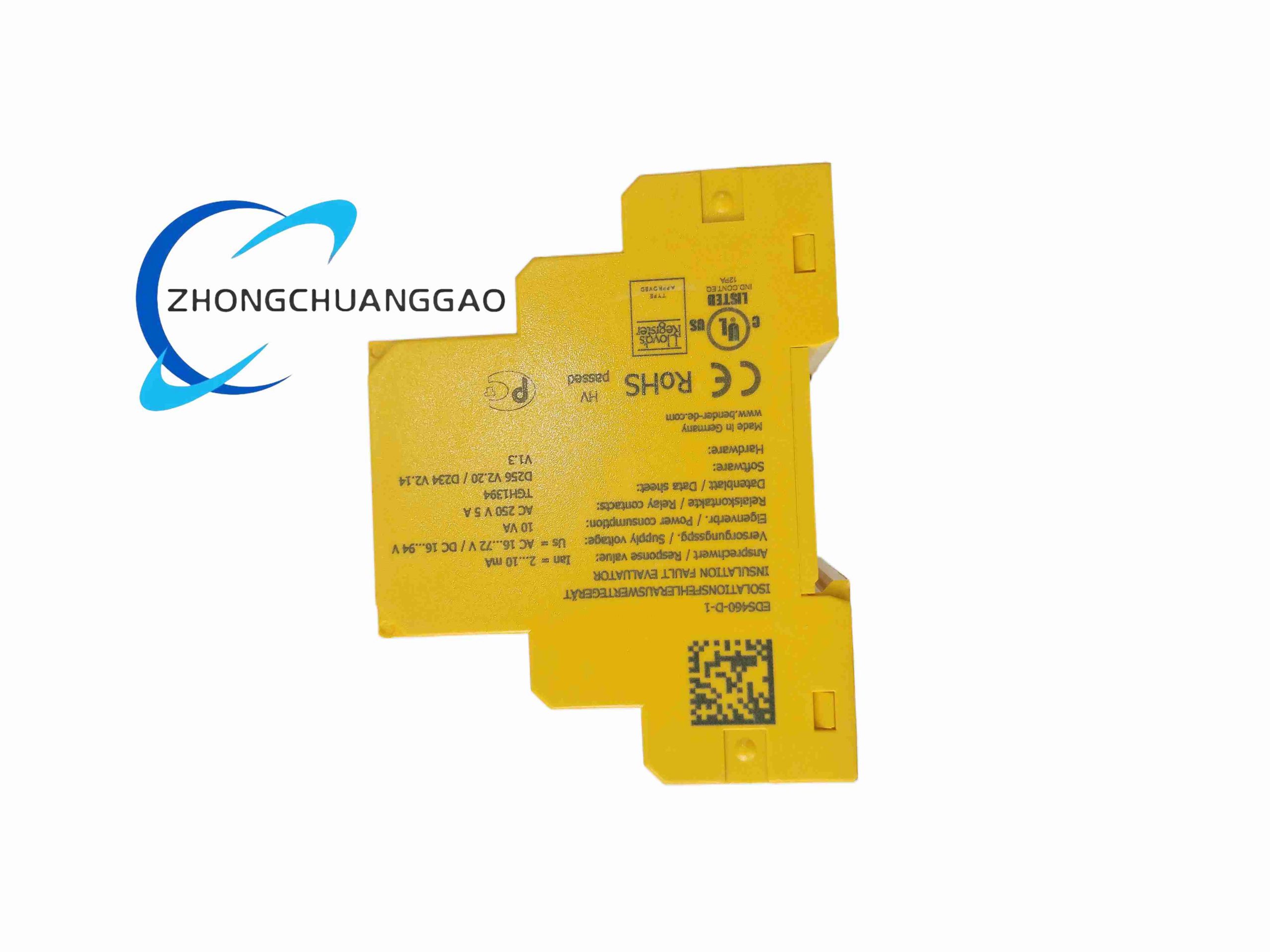
AC 16 to 72 V
DC 16 to 94 V
Frequency: 42 to 460 Hz
Response Sensitivity
EDS function: 2 to 10 mA adjustable
EDS measuring range: 1.5 to 50 mA
RCM measuring range: 100 mA to 10 A
Measuring Channels
12 channels per device
Up to 90 EDS devices on BMS bus
Up to 1080 monitored circuits
Scanning
Parallel scanning of all channels
Full scan time: up to approximately 10 seconds in parallel-scan descriptions
Display
Backlit graphical LCD
Local status viewing
Parameter configuration
Plain-text fault channel identification
Alarm Outputs
2 common alarm relays, changeover contacts
12 channel alarm contacts, normally open
Relay rating: up to 5 A at 230 VAC depending on utilization category
Memory
300 event records with date and time
Fault memory selectable latching or non-latching
Communication
RS-485
BMS protocol
Address range 1 to 90
Monitoring Functions
CT connection monitoring
Wire-break detection
External test button support
External reset button support
Mechanical
DIN-rail mounting
Polycarbonate housing
Internal electronics IP30
Terminals IP20
Weight: less than 360 g
Standards
IEC 61557-8
IEC 61557-9
IEC 61326-2-4
DIN EN 60664-1
Application Scenarios
Industrial IT power systems
Medical IT systems
Operating rooms
ICU power systems
Marine distribution
Offshore platforms
Data centers
Photovoltaic DC systems
Power plant auxiliary systems
Working Principle
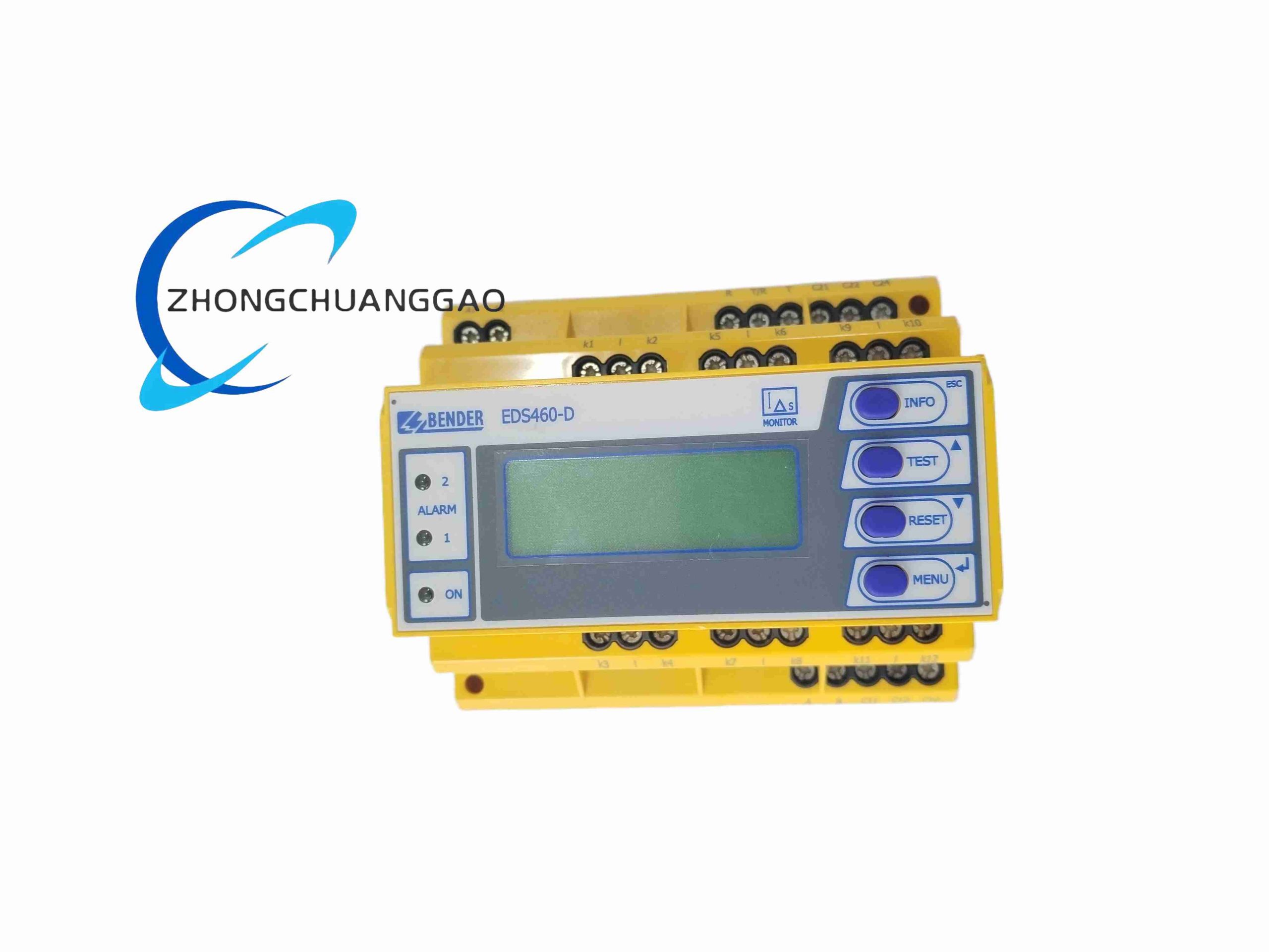
When an insulation fault occurs, the insulation monitor injects a locating current. Measuring current transformers on each branch detect the current. The EDS460-D-1 evaluates the signals, identifies the faulty circuit, activates the corresponding alarm contact, and shows the result on the display.
Installation Requirements
Mount on DIN rail inside a suitable enclosure.
Install measuring current transformers on each monitored feeder.
Connect CT wiring according to Bender wiring rules.
Use shielded RS-485 cable in noisy environments.
Confirm supply voltage matches AC/DC rating.
Usage Notes
Do not test insulation while critical loads are unprotected.
Verify CT orientation during commissioning.
Check CT connection alarm before relying on fault location.
Reset fault memory after corrective maintenance.
Keep BMS termination correct on the RS-485 bus.