Technical Specifications
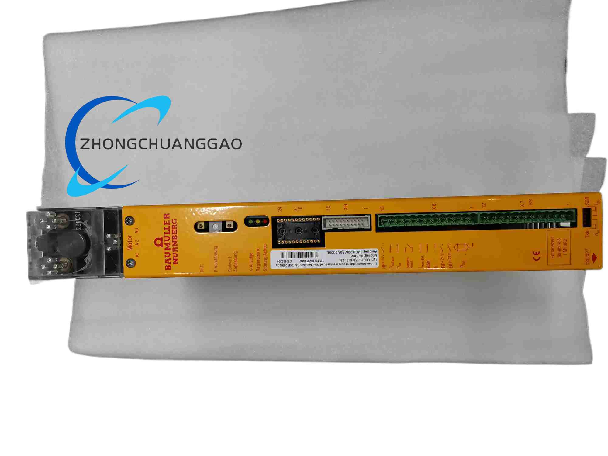
Interpreted continuous current 7.5 A and peak current 15 A from the 7,515 power designation, servo control modes torque, speed and position, feedback support resolver, EnDat and incremental encoder according to option, fieldbus and I/O configuration according to option code 31-224, industrial cabinet operating temperature typically 0 to 55°C, IP20 cabinet-mounted construction.
Functional Features
Closed-loop current regulation, speed and position controllers, motor auto-commissioning, fault diagnostics with coded alarms, regenerative or brake-control support according to power stage, safe-stop functions where the option is fitted.
Application Scenarios
Packaging machines, printing systems, textile machinery, general servo axis automation, retrofit drives for Baumuller motor families, moderate-power positioning systems.
Performance Parameters
7.5 A continuous and 15 A peak output, resolver or absolute encoder feedback, real-time fieldbus command input according to option, rapid current-loop response, thermal and overcurrent protection.
Material Composition
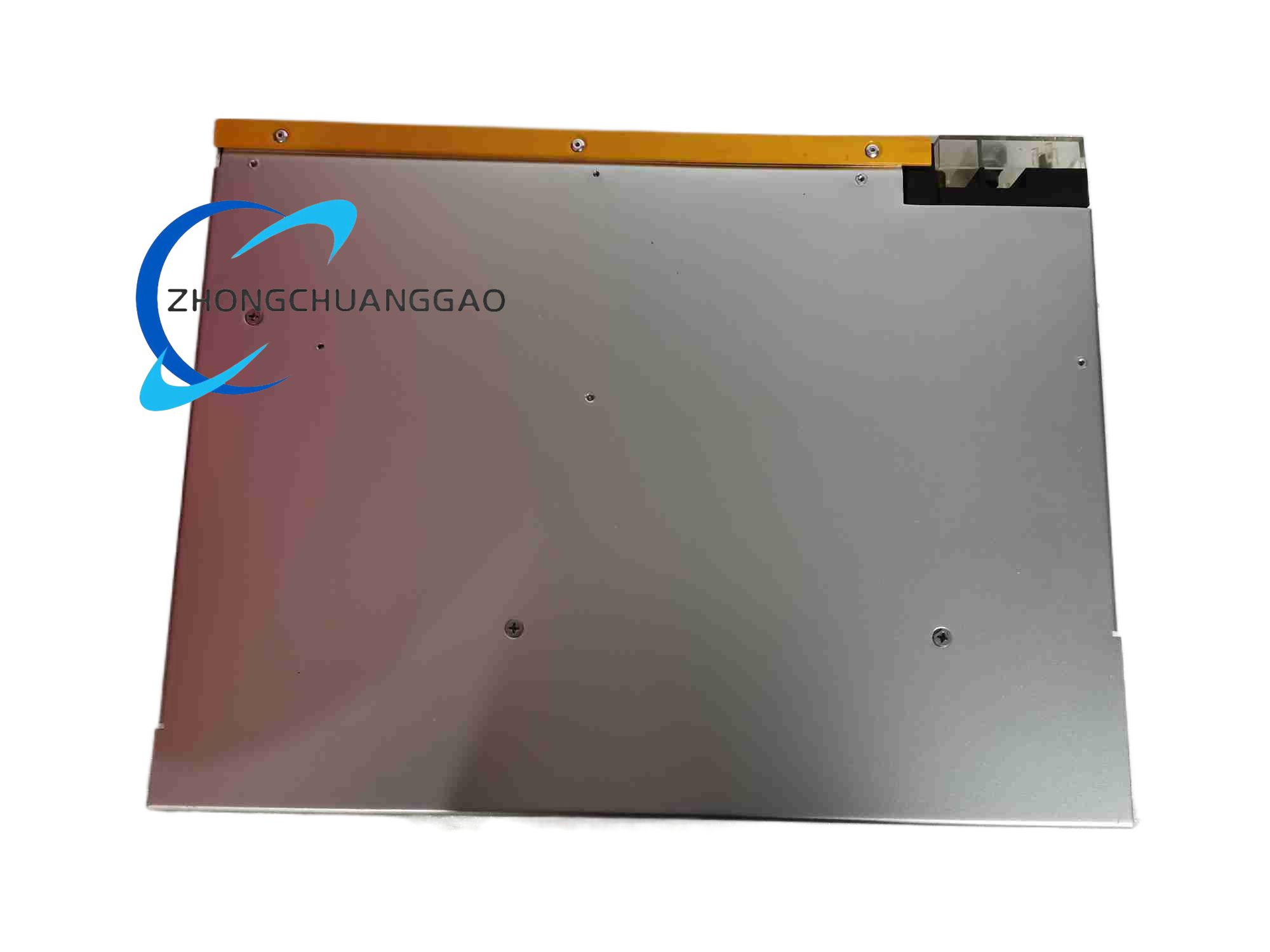
Aluminium or steel drive housing according to variant, copper power terminals, DBC IGBT substrate, FR4 control PCB with industrial coating, silver or nickel contact relay and I/O elements.
Structural Characteristics
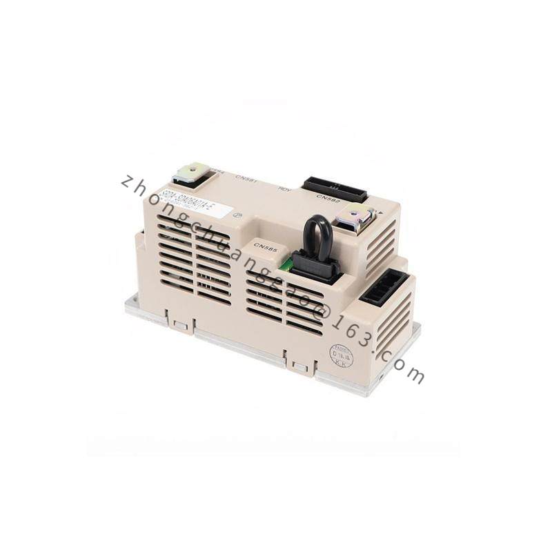
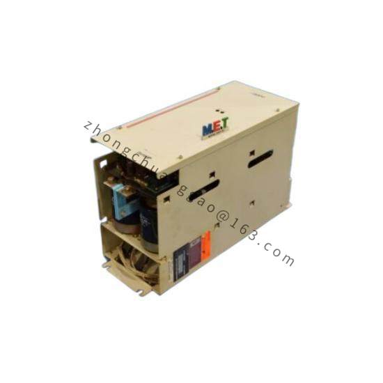
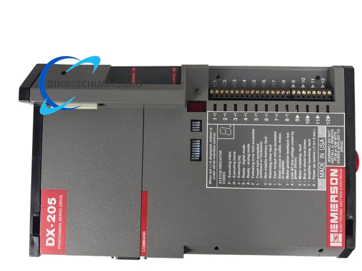
Cabinet-mount servo module, front status and fault indicators, rear DC-bus and motor power terminals, separate encoder and I/O connector section, option-card slot or firmware option area for bus communication.
Working Principle
The controller sends setpoint and enable commands over the fieldbus or analog/digital interface. The drive regulates IGBT output from the DC bus to produce three-phase motor current. Feedback devices return position and speed data; the internal loops adjust torque, velocity and position until the actual values match the command.
Installation Requirements
Mount in a grounded control cabinet with adequate ventilation. Connect the DC bus or rectifier supply according to the BUS21L power stage. Use shielded motor and encoder cables with proper separation from power wiring. Configure the option code, motor parameters and feedback type before first energization.
Usage Precautions
Do not exceed the continuous 7.5 A rating without derating analysis. Verify encoder type before auto-commissioning. Clear fault codes using the Baumuller diagnostic procedure rather than repeated resetting. Inspect brake control and thermal protection regularly. Confirm option 31-224 firmware and hardware compatibility with the existing control architecture.