Technical Specifications
Manufacturer: Applied Power Systems
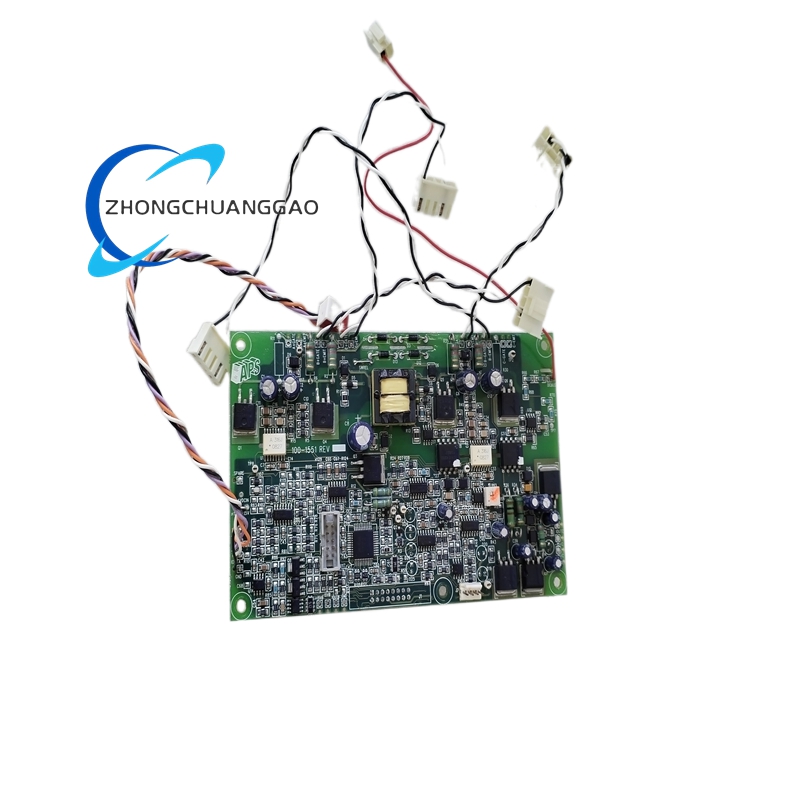
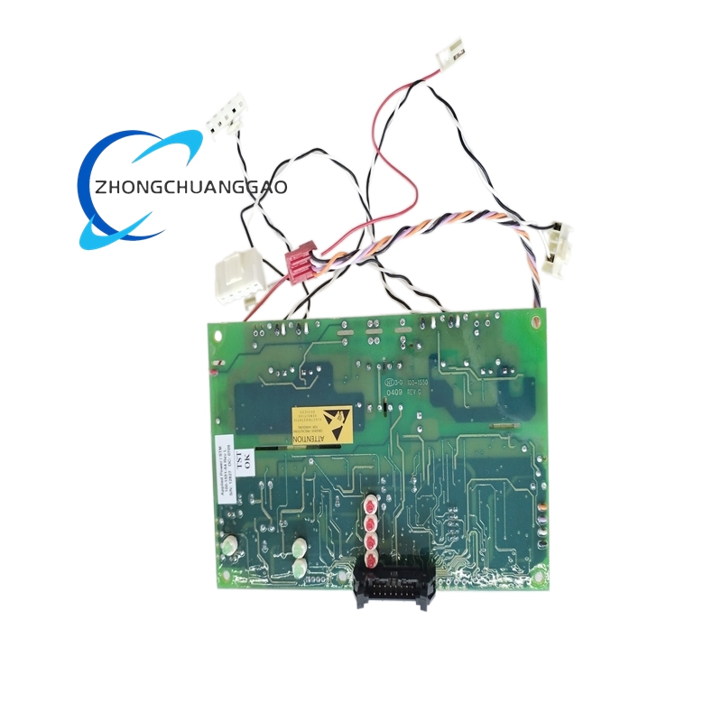
Board family: 100-1551
Documented revision: Rev L
Reported board markings: 100-1551-54, 100-1551, AP-2161A, 100-2160A, TMPSNS
Reported board weight: approximately 160 g
Input voltage: not established from public board data
Output rating: not established from public board data
Communication protocol: not established from public board data
Function Features
Provides gate-control logic and interface between controller commands and power-device drive stages. Supports bench verification in compatible APS fixtures, resistance checks on power rails, initialization confirmation, gate-command simulation, driver-response measurement, and feedback validation.
Structure
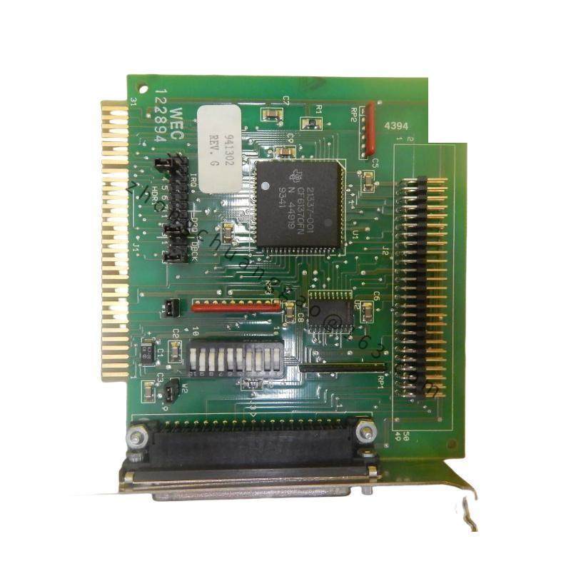
Printed circuit board with gate-drive components, connector interfaces, possibly driver ICs and sensing circuits. Reported related markings indicate temperature-sense and auxiliary control sections, but exact component layout must be confirmed from the physical board.
Working Principle
Control logic issues gate commands; driver stage transfers the commands to power semiconductors; feedback and protection circuits monitor status. Exact switching parameters depend on the host APS power assembly and are not defined by the bare board number alone.
Installation Requirements
Install only in the compatible APS assembly or approved engineering fixture. Record part number, revision, serial or date code, assembly markings, connector configuration, IC and driver markings, jumper or DIP positions. Use ESD packaging and ESD-safe handling.
Usage Notes
Do not energize without confirming revision and host compatibility. Perform rail-resistance checks before power application. Use oscilloscope verification for gate timing. Do not substitute generic PLC test racks for functional acceptance.