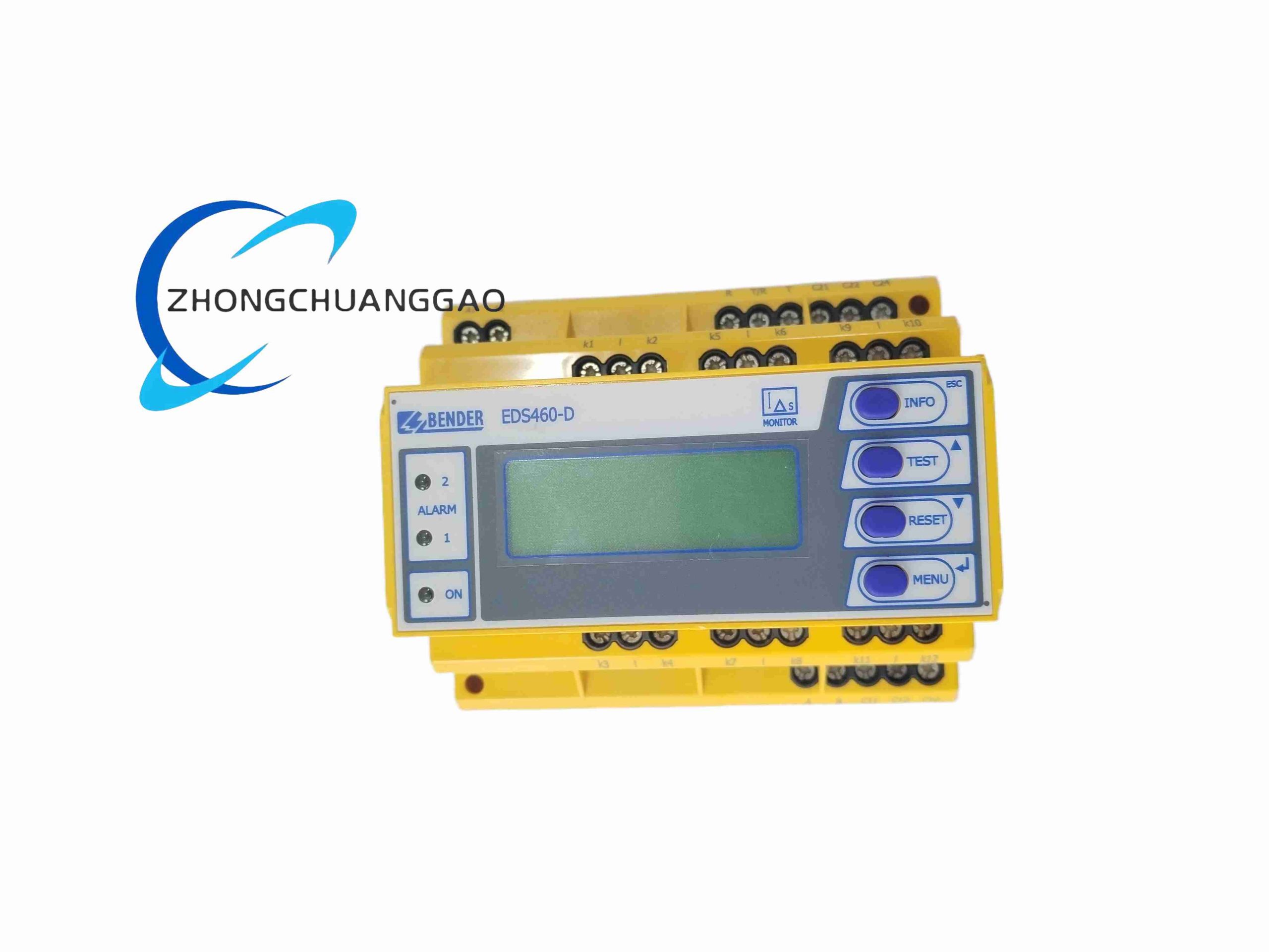
Product Name
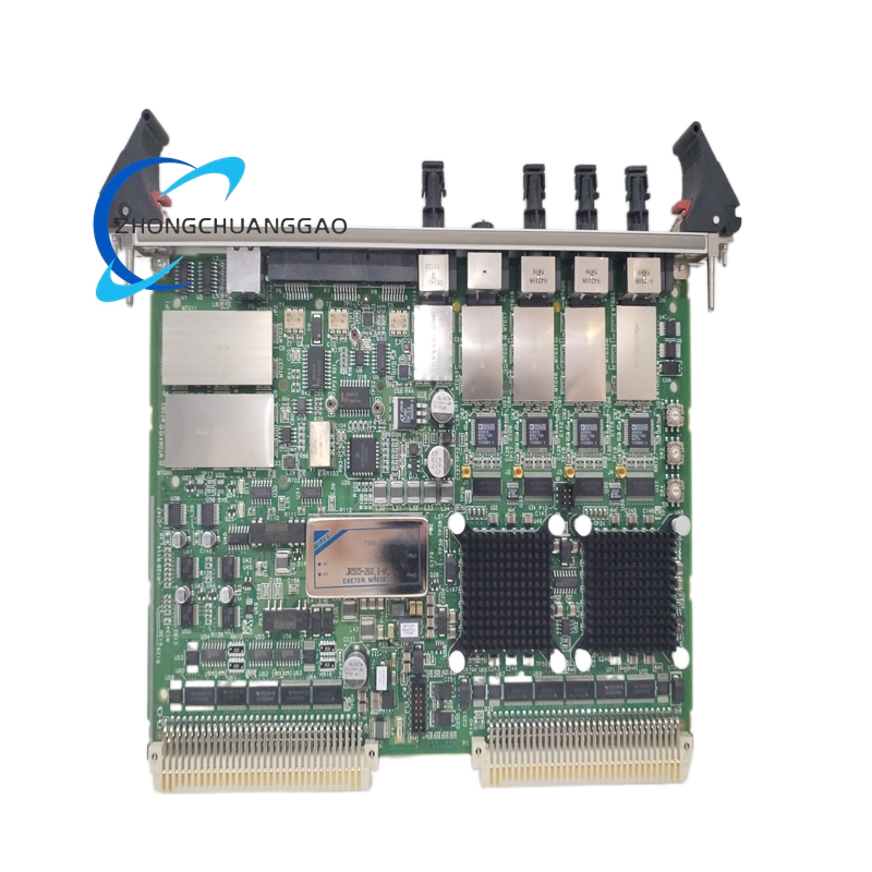
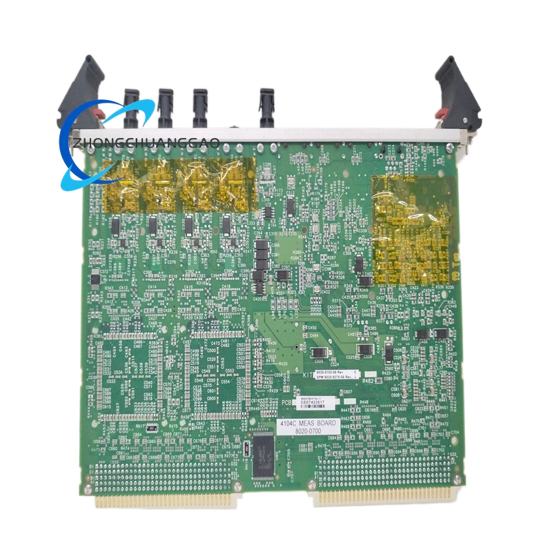
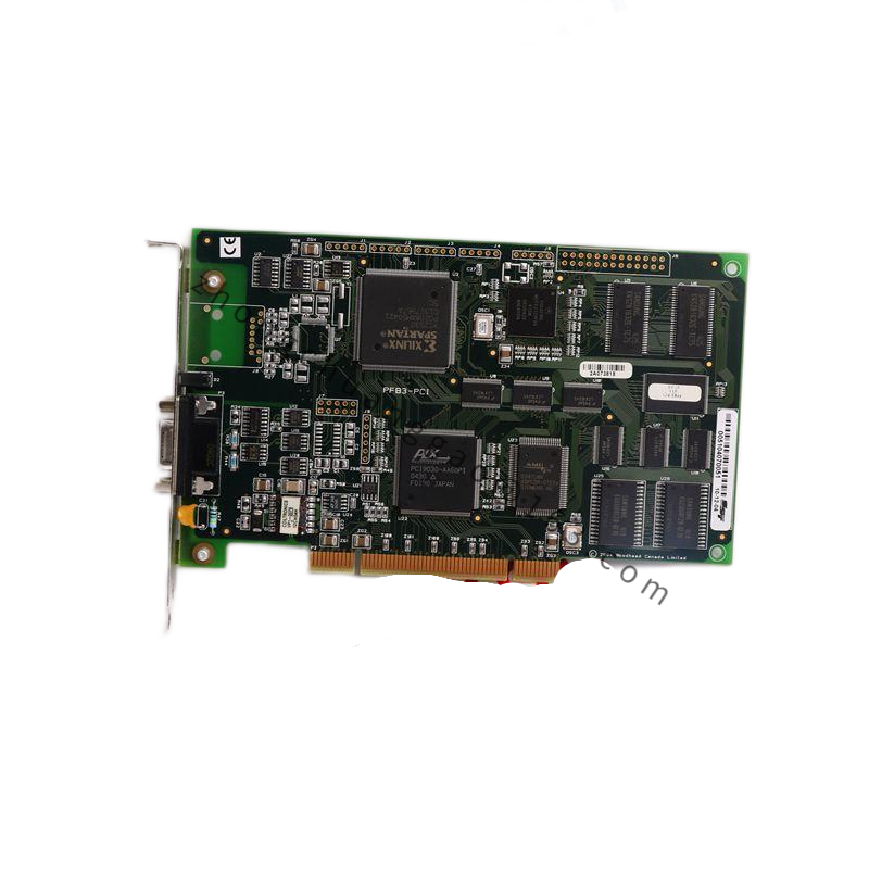
ZMI-4104C four channel heterodyne laser interferometer measurement board.
Product Introduction
This board processes optical heterodyne signals from Zygo laser interferometers and converts them into high resolution displacement data for multi axis precision motion systems. It is designed for semiconductor lithography stages, wafer inspection platforms, optical alignment systems and ultra precision machining.
Technical Specifications
Measurement Axes
Four independent interferometer channels.
Board Form Factor
6U VME64x single board.
Position Resolution
0.15 nm in double pass interferometer configuration.
Maximum Axis Velocity
Plus or minus 2.55 m/s.
Accuracy At Maximum Velocity
0.2 nm sigma.
Minimum Optical Input Power
0.07 microwatts.
Compatible Lasers
Zygo ZMI 7702, 7714 and 7724 heterodyne laser sources.
System Scalability
Up to 64 axes in one VME chassis using multiple boards.
Operating Temperature
0 to 40 degrees Celsius under controlled laboratory conditions.
Functional Features
Real Time Demodulation
Decodes quadrature heterodyne signals from four probes simultaneously.
Cyclic Error Compensation
Applies correction algorithms to reduce nonlinear optical measurement error.
Environmental Compensation
Uses attached air temperature, pressure and humidity sensors to correct refractive index.
High Speed Sampling
Supports dynamic displacement measurement with low noise output to the motion controller.
Application Scenarios
Semiconductor Lithography
Wafer stage and reticle stage nanometer level position feedback.
Precision Machining
Tool position monitoring on ultra precision mills and diamond turning machines.
Metrology Laboratories
Calibration of linear stages, optics benches and vibration isolation systems.
Performance Parameters
Signal Processing
Phase interpolation and Doppler frequency decoding with subnanometer output.
Data Output
Digital displacement data transferred over VME64x backplane to host controller.
Noise Floor
Subnanometer level under stabilized optical and environmental conditions.
Structural Features
Front Panel
Hard anodized aluminum panel with status indicators and connector access.
Main Board
Rear mounted PCB with interferometer signal inputs, VME interface and power circuits.
Optical Inputs
Fiber or receiver interfaces matched to Zygo interferometer modules.
Material Composition
PCB Substrate
FR4 high Tg flame retardant laminate with UL94 V0 rating.
Conductive Traces
Oxygen free copper with immersion gold surface finish.
Connectors
Beryllium copper VME gold fingers with durable plating.
Fasteners
Stainless steel screws and dowel pins.
Insulators
Engineering plastic spacers with high thermal stability.
Working Principle
A Zygo heterodyne laser sends reference and measurement beams to remote interferometers. Reflected optical signals return to the board receivers, produce Doppler shifted interference, convert to electrical quadrature signals, undergo phase demodulation, cyclic error correction and environmental refractive index compensation, then output calibrated displacement values for each axis.
Installation Requirements
Power down the VME chassis before inserting the board. Seat the unit in a compatible 6U VME64x slot. Connect laser receiver fibers to the correct channel ports. Install external environmental sensors for air temperature, pressure and humidity. Configure axis mapping, interferometer type and refractive index parameters in Zygo host software.
Usage Precautions
Never insert or remove the board under live backplane power. Verify laser wavelength and receiver model before operation. Maintain optical connectors clean and dust free. Perform periodic calibration after any optical path change. Ensure chassis cooling meets board thermal requirements.