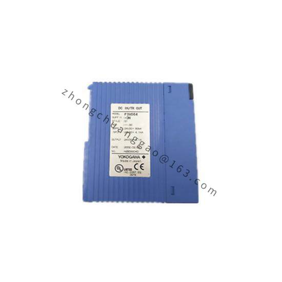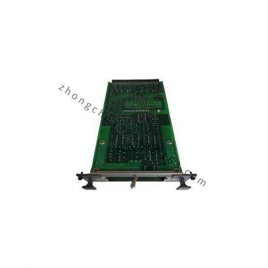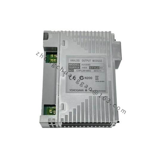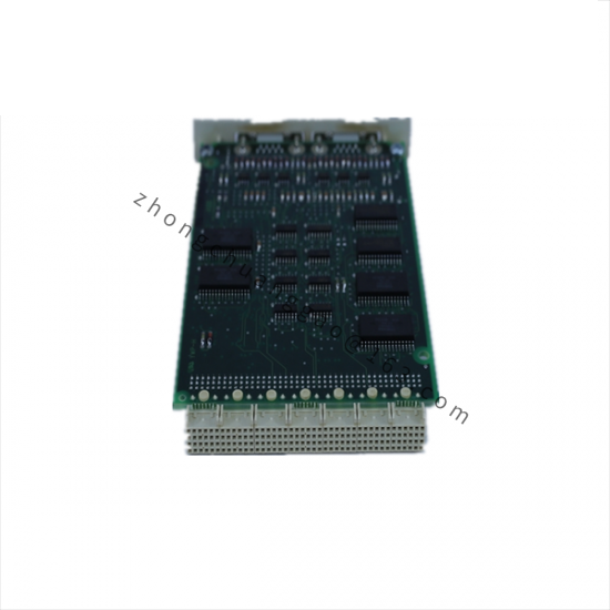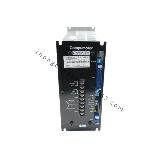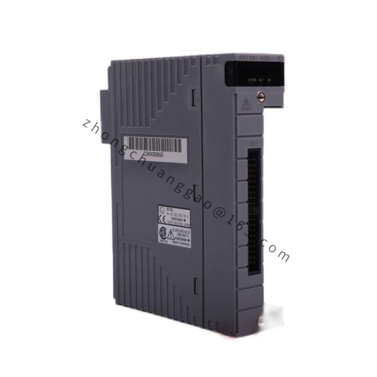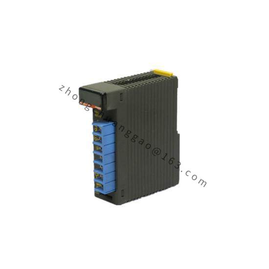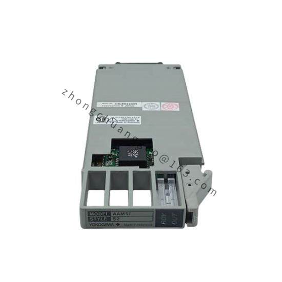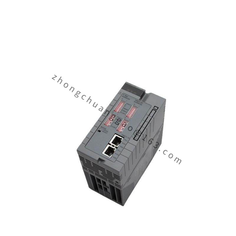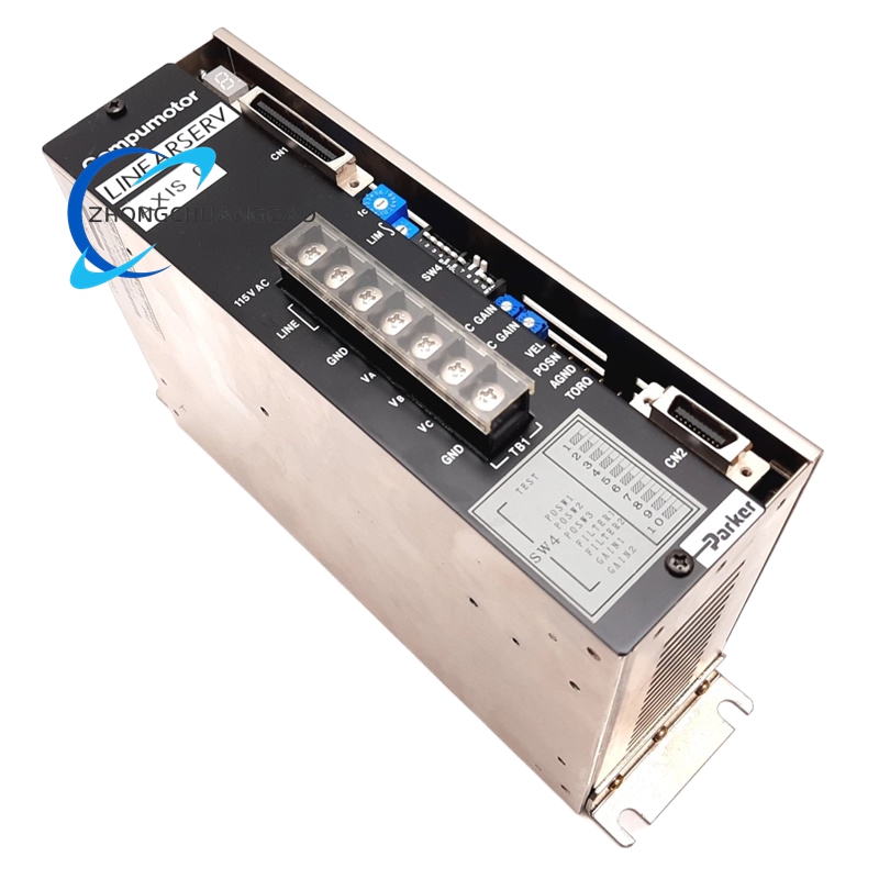


Yokogawa YS17YS1700
Model Number: YS17YS1700
Product Introduction:
The YS17YS1700 is a loop-powered isolated signal converter from Yokogawa’s YS1700 series. It provides galvanic isolation between input and output 4–20 mA signal loops, eliminating ground loop interference in process instrumentation systems.
Detailed content
Function Features:
- Input signal: 4–20 mA DC (2-wire)
- Output signal: 4–20 mA DC (2-wire, loop-powered)
- Galvanic isolation between input and output circuits
- Linear signal conversion with adjustable zero and span
- Loop-powered operation (no external power supply required)
- DIN rail mounting (35 mm)
- Wide operating temperature range for harsh environments
Technical Specifications:
| Parameter | Specification |
|---|---|
| Input Signal | 4–20 mA DC (2-wire) |
| Output Signal | 4–20 mA DC (2-wire, loop-powered) |
| Isolation Voltage | 1500 V AC (50/60 Hz, 1 minute) |
| Isolation Resistance | ≥ 100 MΩ at 500 V DC |
| Accuracy | ±0.1% of span (typical), ±0.2% of span (max) |
| Temperature Drift | ±0.01% of span/°C (typical) |
| Response Time | ≤ 100 ms (0–90% step response) |
| Load Resistance | Maximum 600 Ω (at 24 V DC supply) |
| Operating Voltage | 18–32 V DC (loop-powered) |
| Operating Temperature | -25°C to +70°C |
| Protection Rating | IP20 (front panel) |
| Dimensions (W×H×D) | 22.5 × 90 × 115 mm (approx.) |
| Weight | Approximately 0.1 kg |
| Compliance Standards | CE Marking, RoHS Directive |
Material Composition:
- Housing: Polycarbonate (PC) flame-retardant, UL94 V-0 rated
- Terminal blocks: Phosphor bronze with tin plating
- Internal components: Conformal-coated PCB, metal film resistors
Structure Characteristics:
- Slim DIN rail form factor (22.5 mm width)
- Screw-terminal connections for input and output loops
- Zero and span adjustment potentiometers accessible from front
- LED indicator for power-on status
- Spring-clip terminal blocks for tool-free wiring
Working Principle:
The input 4–20 mA signal is converted to a proportional voltage by a precision shunt resistor. This voltage is amplified and conditioned by an isolation amplifier circuit (typically using optical or magnetic isolation technology). The conditioned signal is then converted back to a 4–20 mA output current using a V-to-I converter. The isolation barrier prevents any DC current path between input and output, breaking ground loops while maintaining signal accuracy.
Advantages & Highlights:
- True galvanic isolation eliminates ground loop errors completely
- Loop-powered design reduces wiring complexity (no external power needed)
- High accuracy (±0.1%) suitable for precision process control
- Wide temperature range (-25°C to +70°C) for outdoor and extreme environments
- Ultra-slim 22.5 mm width saves panel space
Applicable Industries:
- Oil & Gas (wellhead monitoring, pipeline SCADA)
- Chemical processing (reactor control, distillation columns)
- Water treatment (flow, level, pressure transmission)
- HVAC systems (building automation)
- Food & Beverage (batch process control)
- Mining & Minerals (remote sensor signal conditioning)
Installation Requirements:
- Mount on DIN 35 mm rail in control panel or field junction box
- Input loop and output loop must have separate ground references
- Use shielded twisted-pair cable for both input and output wiring
- Maximum cable length: 1000 m (at 24 V DC, 600 Ω load)
- Ensure loop supply voltage ≥ 18 V DC for proper operation
Usage Precautions:
- Do not exceed 600 Ω total loop resistance (output side)
- Do not apply voltage > 32 V DC to the converter terminals
- Input and output grounds must remain isolated (do not bridge)
- Zero/span potentiometers should be adjusted only during commissioning
- Do not expose to direct sunlight or temperatures exceeding 70°C