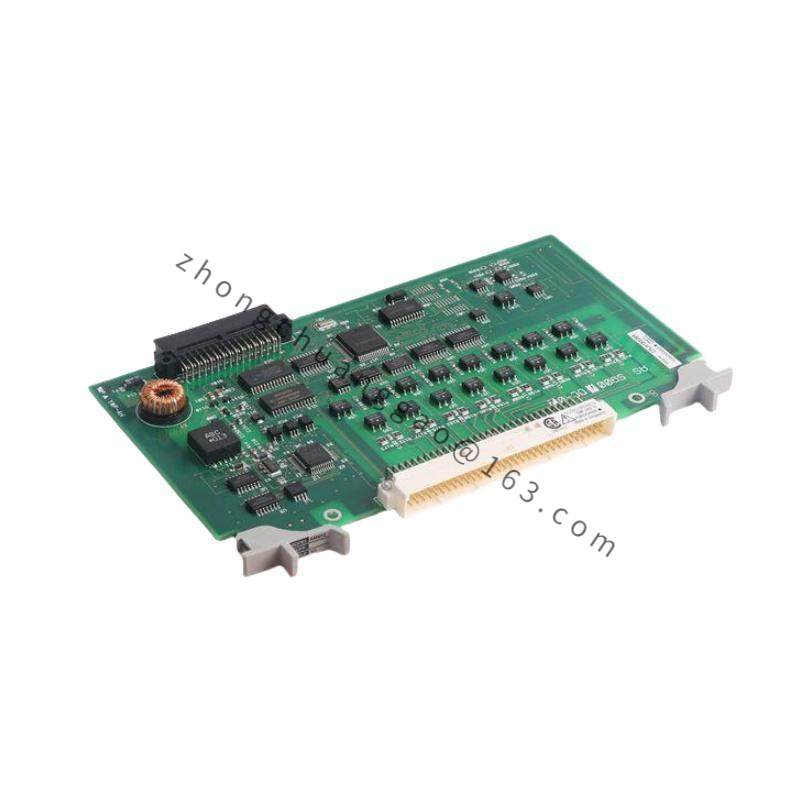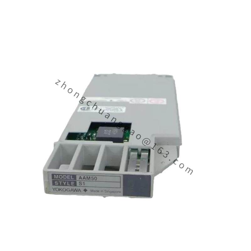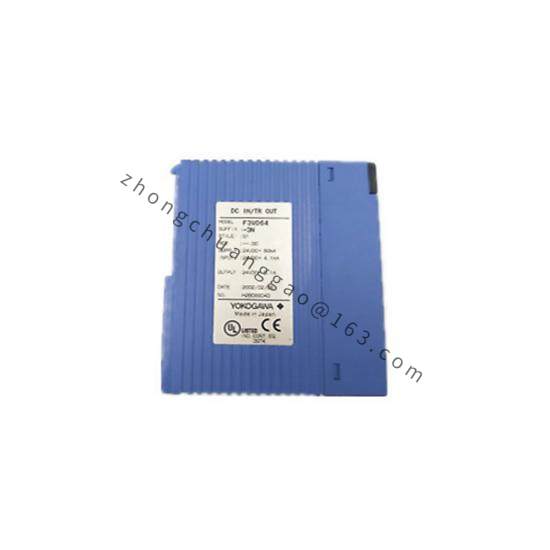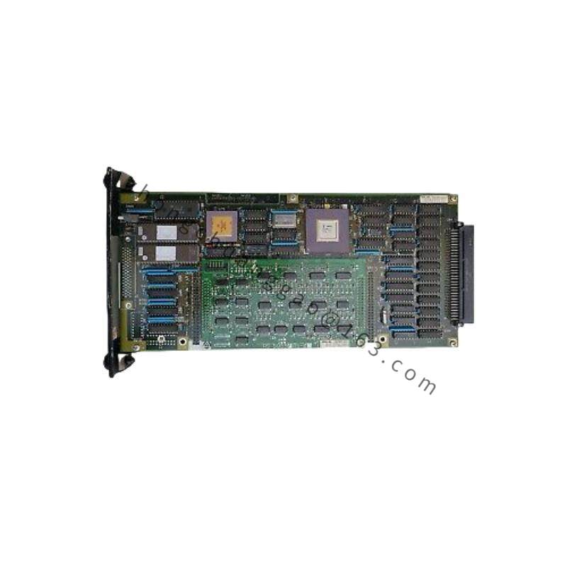


Yokogawa YS1700-101-A34
Product Overview:
The Yokogawa YS1700-101-A34 is a 2-wire vibration transmitter from the YS1700 series. It converts vibration signals from piezoelectric velocity or IEPE acceleration sensors into a 4–20 mA DC output proportional to vibration velocity or acceleration. The “101” indicates the measurement type (velocity, 4–20 mA output), and “A34” specifies the configuration parameters including range and filter settings.
Detailed content
Technical Specifications:
- Measurement Type: Vibration velocity (true RMS) or acceleration (with IEPE input)
- Output Signal: 4–20 mA DC (2-wire, loop-powered)
- Frequency Range: 10 Hz to 1000 Hz (velocity), 10 Hz to 10,000 Hz (acceleration)
- Measurement Range: 0 to 25 mm/s (velocity), 0 to 50 g (acceleration) — configurable
- Accuracy: ±1% of full scale (velocity), ±2% of full scale (acceleration)
- Power Supply: 18–30 V DC (loop-powered)
- Current Consumption: ≤ 20 mA (typical 16 mA at 24 V DC)
- Output Load: Up to 600 Ω
- Protection Rating: IP66/IP67 (NEMA 4X)
- Certification: Intrinsically Safe (Ex ia IIC T6 Ga), ATEX, IECEx, FM
- Operating Temperature: -40°C to +85°C
- Dimensions: 72 × 115 × 90 mm (W × H × D)
- Weight: Approximately 0.5 kg
- Sensor Input: Piezoelectric velocity sensor (mV/mm/s) or IEPE acceleration sensor
Functional Features:
- True RMS measurement for accurate vibration assessment
- Configurable low-pass filter (10 Hz to 1 kHz)
- Configurable alarm setpoints (HH, H, L, LL) with relay output option
- HART 7 communication for remote configuration
- Zero and span adjustment via HART or local potentiometer
- DC offset output for trend monitoring
Performance Parameters:
- Linearity: ±0.5% of full scale
- Temperature Drift: ±0.02% of full scale per °C
- Response Time: < 100 ms
- Overload Protection: 200% of full scale (no damage)
- EMC Compliance: IEC 61326-1, EN 61326-1
Material Composition:
- Housing: Die-cast aluminum alloy with epoxy powder coating
- Connector: M12 × 1, 4-pin (standard for sensor connection)
- Terminal block: Phoenix Contact-compatible screw terminals
- Cable gland: Nickel-plated brass with FKM (Viton) seal
- PCB: Conformal-coated for moisture resistance
Structural Features:
- Compact DIN rail or wall-mount design
- M12 sensor connector on top
- Screw terminal block on the bottom for loop wiring
- LED indicators for power, alarm, and communication status
- HART communication terminals
Working Principle:
The YS1700 receives a raw vibration signal from a piezoelectric velocity sensor or IEPE acceleration sensor. The signal is conditioned (amplified, filtered, and RMS-converted) by the internal signal processor. The processed signal is linearly scaled to a 4–20 mA output current. For velocity measurement, the piezoelectric sensor generates a voltage proportional to vibration velocity (mV/mm/s). The transmitter converts this to a 4–20 mA output where 4 mA = 0 mm/s and 20 mA = full scale. HART communication superimposes digital data on the 4–20 mA loop for remote configuration and diagnostics.
Advantages & Highlights:
- True RMS measurement provides accurate vibration severity assessment
- 2-wire loop-powered design simplifies wiring (no separate power supply needed)
- Intrinsically safe for Zone 0/1 installation on rotating machinery
- Configurable filter eliminates high-frequency noise
- HART communication enables remote calibration and diagnostics
- Wide operating temperature range (-40°C to +85°C) for harsh environments
Applicable Industries:
- Oil and gas (pumps, compressors, turbines)
- Power generation (steam turbines, generators, fans)
- Mining (crushers, conveyors, mills)
- Pulp and paper (rollers, dryers)
- Steel and metals (rolling mills, motors)
- Water and wastewater (pumps, blowers)
Installation Requirements:
- Mount the transmitter as close as possible to the vibration sensor (maximum 10 meters cable length recommended)
- Use shielded twisted-pair cable for sensor connection
- Ground the transmitter housing and cable shield at one end only
- Configure the measurement range and filter in the DCS/SCADA to match the transmitter settings
- Verify the sensor type (velocity vs. IEPE) matches the transmitter input configuration
Usage Precautions:
- Do not apply voltage to the sensor input terminals (the transmitter provides excitation for IEPE sensors only)
- Do not exceed the maximum input signal (500 mV for velocity sensors)
- Perform zero calibration with the machine stopped (no vibration)
- Check the 4–20 mA output with a calibrated milliammeter during commissioning
- Replace the transmitter if the output drift exceeds ±2% of full scale