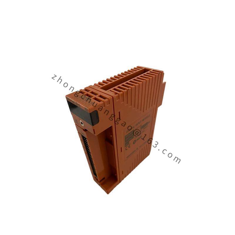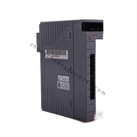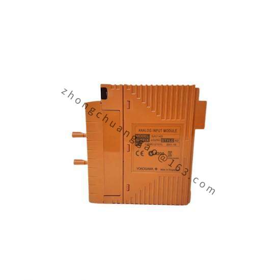
Yokogawa YS1310-121/A06
Product Overview:
The YS1310-121/A06 is a smart differential pressure (DP) or pressure transmitter from Yokogawa’s YS1000 series. It features a silicon resonant sensor for high accuracy and long-term stability. The transmitter supports HART 7, Foundation Fieldbus (FF), Profibus PA, and Modbus RTU communication protocols, making it suitable for integration with any DCS or PLC system.
Detailed content
Technical Specifications:
| Parameter | Value |
|---|---|
| Measurement Type | Differential Pressure (DP) / Gauge Pressure / Absolute Pressure |
| Sensor Type | Silicon Resonant Sensor (Single Crystal Silicon) |
| Range Code 121 | 0 to 25 kPa (0 to 100 inH₂O) — see note below for full range table |
| Accuracy (Reference) | ±0.04% of URL (Upper Range Limit) |
| Turndown Ratio | 100:1 (adjustable) |
| Output Signal (A06) | 4-20 mA DC (HART 7 superimposed) |
| Damping | Adjustable: 0.1 to 32 seconds (default: 1.0 second) |
| Operating Temperature (Ambient) | -40°C to +85°C |
| Process Temperature | -40°C to +120°C (standard), up to +200°C (high-temp option) |
| Process Pressure (Static) | Up to 16 MPa (2320 psi) |
| Overpressure Rating | 1.5 × URL (standard), up to 40 MPa absolute maximum |
| Power Supply | 12 V DC to 45 V DC (HART communication requires minimum 12V DC at 23mA) |
| Power Consumption | Maximum 30 mA (at 24V DC, with HART communication active) |
| Protocols | HART 7, Foundation Fieldbus H1, Profibus PA, Modbus RTU (selectable via configuration) |
| Enclosure Material (Wetted Parts) | 316L Stainless Steel |
| Enclosure Material (Electronics Housing) | Aluminum alloy (painted), Polycarbonate (optional) |
| Process Connection | 1/2 NPT Male (standard), other options available: 1/4 NPT, 1/2 BSP, M20×1.5, flanged (DN50, DN80) |
| Protection Rating | IP67 (NEMA 4X) |
| Explosion Proof | ATEX Zone 1/2, Zone 21/22 (optional with Ex d or Ex ia certification) |
| SIL Rating | SIL 2 (IEC 61508, for safety applications with appropriate configuration) |
| Certifications | CE, FM, CSA, ATEX, IECEx, EAC, TIIS |
| Dimensions (Approximate) | Ø 72 mm × 155 mm (with 1/2 NPT connection) |
| Weight (Approximate) | Approximately 1.8 kg (with 1/2 NPT connection) |
| Diaphragm Material | 316L Stainless Steel, Hastelloy C-276 (optional), Tantalum (optional), Monel (optional) |
| Fill Fluid | Silicone Oil (standard), Fluorinated Oil (high-temp option), Halocarbon (food-grade option) |
Range Code 121 Reference (YS1310):
| Range Code | Differential Pressure Range |
|---|---|
| 000 | 0 to 2.5 kPa |
| 010 | 0 to 10 kPa |
| 020 | 0 to 20 kPa |
| 050 | 0 to 50 kPa |
| 100 | 0 to 100 kPa |
| 121 | 0 to 25 kPa (0 to 100 inH₂O) |
| 200 | 0 to 200 kPa |
| 500 | 0 to 500 kPa |
| 1000 | 0 to 1000 kPa |
Functional Features:
- Silicon resonant sensor: Provides ±0.04% accuracy with excellent long-term stability (±0.04% per 10 years)
- Multi-protocol communication: HART 7, FF H1, Profibus PA, Modbus RTU — one transmitter fits any system
- Built-in temperature sensor: Measures process temperature for density compensation (in DP flow applications)
- Self-diagnostics: Continuous sensor health monitoring with alarm output on failure
- Zero and span trimming: Adjustable via HART communicator or front panel buttons
- Damping adjustable: 0.1 to 32 seconds to filter process noise
- Quick-mount design: 1/2 NPT connection with integrated 3-valve manifold mounting option
- SIL 2 capable: Suitable for safety-critical applications (SIS)
Working Principle:
The YS1310 uses a silicon resonant sensor consisting of a vibrating silicon diaphragm. The resonant frequency of the diaphragm changes with applied pressure. The sensor electronics measure this frequency shift using a phase-locked loop (PLL) circuit and convert it to a digital pressure value. The 4-20 mA output is generated by a high-precision DAC. HART 7 communication uses FSK modulation (1200/2200 Hz) superimposed on the 4-20 mA signal. For Foundation Fieldbus, the transmitter acts as an FF H1 device with standard AI (Analog Input) and PID function blocks.
Advantages and Highlights:
- ±0.04% accuracy — highest accuracy class in Yokogawa’s transmitter lineup
- Silicon resonant sensor — 10× more stable than capacitive sensors over time
- Multi-protocol (HART/FF/Profibus/Modbus) — universal compatibility with any DCS/PLC
- SIL 2 certified — suitable for safety instrumented functions
- IP67 / NEMA 4X — fully weatherproof for outdoor installation
- Wide turndown (100:1) — one transmitter covers a wide range of applications
- 316L stainless steel wetted parts — corrosion-resistant for harsh process fluids
Applicable Industries:
- Oil and Gas (DP flow measurement, tank level, pressure monitoring)
- Chemical and Petrochemical (reactor pressure, column DP)
- Power Generation (boiler drum level, condenser vacuum)
- Water and Wastewater (filter DP, flow measurement)
- Pharmaceutical (clean-in-place, sanitary applications)
- Food and Beverage (hygienic process monitoring)
- Pulp and Paper (stock flow, white water DP)
Installation Requirements:
- Install the transmitter at or below the pipe tap point for liquid service (to avoid gas pockets)
- Install the transmitter at or above the pipe tap point for gas service (to avoid liquid accumulation)
- Use impulse tubing filled with appropriate fill fluid (silicone oil standard)
- Install a 3-valve manifold between the process taps and the transmitter for isolation
- Connect power supply (12-45V DC) in series with the 4-20 mA loop
- For HART communication: Minimum loop resistance of 230Ω required
- For FF communication: Connect to FF H1 segment via FF interface module (e.g., Yokogawa AFV10D)
- Torque process connection to 35-40 N·m (1/2 NPT) using a torque wrench
Usage Precautions:
- Do not exceed maximum process pressure of 16 MPa (2320 psi) static or 40 MPa burst
- Do not apply pressure exceeding 1.5 × URL — risk of permanent sensor damage
- Verify diaphragm material compatibility with process fluid before installation (consult Yokogawa chemical compatibility chart)
- Perform zero calibration after installation and after any impulse line change
- For HART communication: Ensure loop resistance is 230Ω to 1100Ω
- Do not expose the transmitter to temperatures exceeding +120°C (or +200°C for high-temp version)
- Perform periodic verification every 1-5 years depending on SIL requirement and process criticality
- Do not use impulse tubing longer than 30 meters without a repeater — signal degradation will occur