

Digital guide

You are here:

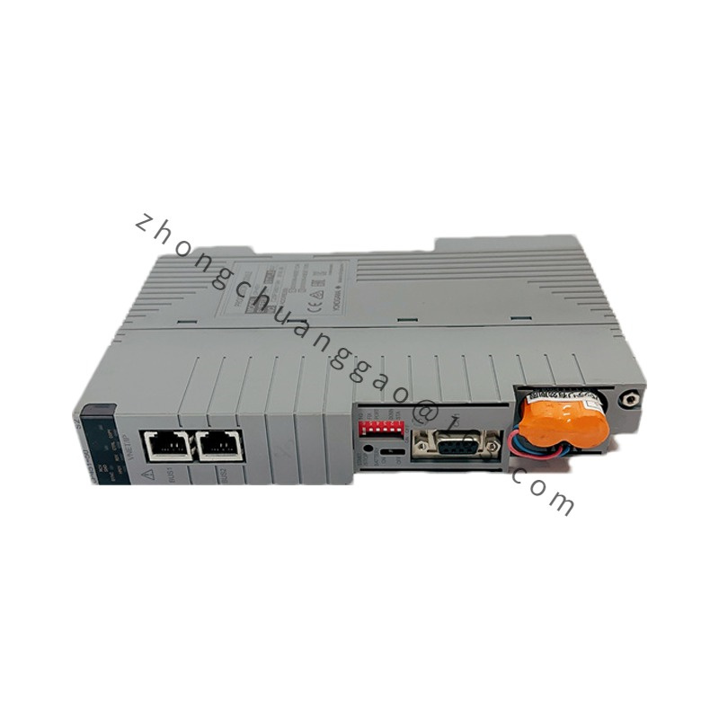
Yokogawa YFCT-1GG3-A1A*A

Product Introduction:
The Yokogawa YFCT-1GG3-A1A*A is a clamp-on (non-invasive) ultrasonic flowmeter designed for liquid flow measurement without cutting the pipe or interrupting process flow. The 1G indicates 1-inch nominal pipe size compatibility. The G3 suffix denotes the specific transducer configuration. The A1A*A specifies the sensor type (A-series transducers) and output configuration. This meter uses the transit-time difference method for highly accurate volumetric flow measurement.

Detailed content

Technical Specifications:

  • Measurement Principle: Transit-time ultrasonic (difference method)
  • Pipe Size Compatibility: 1 inch (DN25) nominal — indicated by “1G”
  • Pipe Size Range: DN15 to DN300 (0.5 to 12 inch) depending on transducer model
  • Pipe Material: Steel, stainless steel, cast iron, PVC, copper, and most other materials
  • Fluid Type: Clean liquids, slurry (limited solids content)
  • Flow Range: 0.01 to 12 m/s (adjustable per pipe size)
  • Accuracy: ±1% of reading (at flow rate ≥0.3 m/s), ±0.5% with calibration
  • Repeatability: ±0.2%
  • Output Signals: 4–20 mA DC, pulse output, RS-485 (Modbus RTU)
  • Power Supply: 100–240 V AC (50/60 Hz) or 24 V DC
  • Display: 8-digit LCD with flow rate, totalizer, velocity, and signal strength bars
  • Operating Temperature (Transducer): -30 to 160 °C (-22 to 320 °F)
  • Operating Temperature (Electronics): -10 to 50 °C (14 to 122 °F)
  • Protection Rating: IP67 (transducer), IP65 (electronics housing)
  • Pipe Wall Thickness: 1.5 to 50 mm (0.06 to 2.0 in)
  • Lining Thickness: Up to 10 mm (0.4 in) compatible
  • Response Time: 1 second (typ.)
  • Data Logging: Up to 2000 data points with timestamp
  • Totalizer: Non-volatile memory, battery-backed (10-year battery life)

Functional Features:

  • Non-Invasive Installation: No pipe cutting, no process interruption, no pressure drop
  • Bi-directional Measurement: Measures flow in both directions automatically
  • Empty Pipe Detection: Alarms when no liquid is present in the pipe
  • Signal Quality Indicator: Real-time display of signal strength for installation optimization
  • Velocity Measurement: Displays average fluid velocity in addition to volumetric flow
  • Pipe Parameter Input: Internal database for 20 common pipe materials and sizes
  • Totalizer: Accumulates total volume with automatic unit conversion

Performance Parameters:

  • Ultrasonic Frequency: 1 MHz (standard for liquid applications)
  • Transit-Time Resolution: 10 picoseconds
  • Minimum Conductivity: 1 μS/cm (with Doppler option); not required for transit-time method
  • Maximum Pressure: Up to 40 MPa (5800 psi) — limited by pipe, not meter
  • Insulation Resistance: 100 MΩ minimum at 500 V DC
  • Dielectric Strength: 1500 V AC for 1 minute
  • Battery Life: 10 years (for totalizer memory backup)

Structural Features:

  • Clamp-on transducer design with adjustable mounting bracket
  • V-clip or chain-clamp mounting option for pipes 1–12 inch
  • Transducer cable length: 5 m (standard), up to 30 m (option)
  • Weatherproof electronics enclosure with DIN rail or wall mount
  • Color LCD display with backlight for outdoor readability
  • Keypad with 4 navigation buttons for local configuration

Working Principle:
The YFCT uses the transit-time difference method. Two ultrasonic transducers are mounted on the outside of the pipe at an angle. One transducer sends an ultrasonic pulse downstream, and the other sends a pulse upstream. The difference in transit time between the two pulses is directly proportional to the average fluid velocity. The meter calculates volumetric flow rate using the equation: Q = K × Δt × D², where K is a calibration constant, Δt is the transit-time difference, and D is the pipe inner diameter. The 4–20 mA output is linearly proportional to the flow rate.

Advantage Highlights:

  • Zero Pipe Modification: No hot tapping, no welding, no process shutdown required for installation
  • No Pressure Drop: Completely non-intrusive measurement
  • Wide Pipe Compatibility: Works on steel, stainless steel, PVC, copper, and lined pipes
  • High Accuracy: ±1% of reading without pipe-specific calibration
  • Battery-Backed Totalizer: Retains totalized flow data even during power outages
  • Signal Quality Indicator: Ensures optimal transducer placement during installation

Applicable Industries:

  • Water and wastewater utilities
  • Chemical processing
  • Power plant cooling water
  • HVAC chiller water systems
  • Oil and gas (clean liquid lines)
  • Food and beverage
  • Pharmaceutical water systems (WFI, PW)
  • Mining slurry transport (low solids)

Installation Requirements:

  • Install on straight pipe section with minimum 10D upstream and 5D downstream (D = pipe diameter)
  • Mount transducers at the 45° or V-method position as per manual
  • Ensure pipe surface is clean, dry, and free of paint or heavy scaling at transducer location
  • Apply coupling gel between transducer and pipe surface for acoustic contact
  • Use the signal strength indicator during installation to optimize transducer position
  • Avoid installing near pumps, valves, or pipe elbows (minimum 10D distance)

Usage Precautions:

  • Do not install on pipes with heavy internal scaling or thick lining (>10 mm) without verification
  • Ensure pipe is completely full of liquid for accurate measurement (no air pockets)
  • Avoid installing on pipes with gas bubbles or high solids content (>5% by volume)
  • Re-apply coupling gel if signal quality degrades over time
  • Do not exceed maximum pipe wall thickness of 50 mm for standard transducers
  • Calibrate with known flow rate (e.g., volumetric tank) for highest accuracy (±0.5%)

You may also like