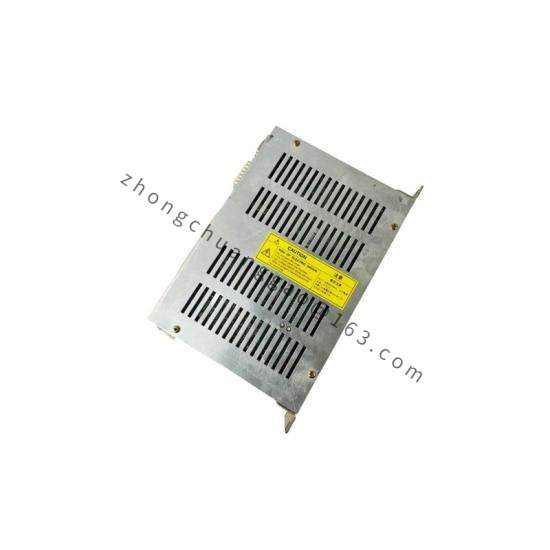

Yokogawa UT150L-RN/EX/Z
Model Number: UT150L-RN/EX/Z
Product Introduction:
The UT150L-RN/EX/Z is a single-loop digital indicating controller from Yokogawa’s UT150 series, designed for temperature, pressure, flow, and level control in hazardous areas. The /EX suffix indicates intrinsically safe (Ex ia) certification, and /Z denotes a specific regional/configuration variant.
Detailed content
Function Features:
- Single-loop PID control (PID, ON/OFF, 2-position control)
- Universal input: TC (Type K, J, T, E, R, S, B, N), RTD (Pt100, JPt100, Cu50), mA, V, mV
- Relay output (RN): 2 SPDT relays (alarm 1, alarm 2) + 1 SPDT relay (control output)
- Large 5-digit LED display (14.2 mm digit height) with bar graph
- Intrinsically safe (Ex ia IIC T6 Ga) for Zone 0/1 hazardous areas
- Auto-tuning PID function
- Heater burnout alarm (HBA) for TC inputs
- Sensor break alarm (SBA)
Technical Specifications:
| Parameter | Specification |
|---|---|
| Control Output | Relay (RN = Relay N type: 3 relays total) |
| Number of Relays | 3 SPDT relays (1 control + 2 alarm) |
| Relay Rating | 3 A at 250 V AC (resistive), 30 V DC (resistive) |
| Input Type | Universal: TC, RTD, 4–20 mA, 0–100 mV, 0–1 V, 0–5 V |
| Control Mode | PID (auto-tuning), ON/OFF, 2-position |
| Control Accuracy | ±0.3% of F.S. (PID), ±0.5% of F.S. (ON/OFF) |
| Display | 5-digit LED (red, 14.2 mm), bar graph |
| Sampling Rate | 200 ms |
| Alarm Functions | HBA, SBA, deviation alarm, absolute value alarm |
| Power Supply | 100–240 V AC (50/60 Hz) or 24 V DC |
| Operating Temperature | -10°C to +55°C |
| Protection Rating | NEMA 4X / IP66 (front panel) |
| Hazardous Area | Ex ia IIC T6 Ga (Zone 0, 1, 2) |
| Dimensions (W×H×D) | 96 × 48 × 112 mm (1/8 DIN cutout: 92 × 45 mm) |
| Weight | Approximately 0.4 kg |
| Compliance Standards | ATEX, IECEx, FM, CSA, SIL 1 (IEC 61508) |
Material Composition:
- Front panel: Polycarbonate (PC) with UV-resistant coating
- Housing: ABS engineering plastic (flame-retardant)
- Terminal blocks: Phosphor bronze, nickel-plated
- Gasket: Silicone rubber (IP66 seal)
Structure Characteristics:
- 1/8 DIN (96 × 48 mm) panel cutout — fits standard instrument panels
- Snap-in front panel for quick removal
- 4-button navigation (UP, DOWN, ENTER, SHIFT)
- Terminal cover with gasket for IP66 protection
- Intrinsically safe barrier terminals (blue-colored for EX marking)
Working Principle:
The input signal (TC, RTD, or analog) is sampled at 200 ms intervals and digitized by a 16-bit A/D converter. The PID algorithm compares the process value (PV) with the setpoint (SV) and calculates the control output. For relay output (RN), the controller energizes or de-energizes the internal relays based on the PID output state (heating/cooling logic). The Ex ia barrier limits the energy (voltage and current) entering the hazardous area to levels below the ignition threshold of the surrounding atmosphere. Auto-tuning applies a step change to the process and analyzes the response to calculate optimal PID parameters (P, I, D) automatically.
Advantages & Highlights:
- Intrinsically safe (Ex ia IIC T6 Ga) — safe for Zone 0 (continuous explosive atmosphere)
- 3 relays provide independent control and dual alarm functions without external relays
- Auto-tuning PID eliminates manual parameter adjustment
- 5-digit large display visible from distance (up to 10 meters)
- Universal input accepts any standard sensor without hardware changes
- IP66 front panel resists washdown and dust ingress
Applicable Industries:
- Oil & Gas (wellhead temperature, separator level, flare gas monitoring)
- Chemical Plants (reactor temperature, storage tank level)
- Pharmaceutical (cleanroom HVAC, autoclave temperature)
- Food & Beverage (pasteurizer control, fermentation temperature)
- Mining (gas detection, conveyor belt monitoring)
- Water Treatment (chlorine dosing, pH control)
Installation Requirements:
- 1/8 DIN panel cutout: 92 × 45 mm (W × H), depth ≥ 100 mm
- Mount with gasket to achieve IP66 rating
- Connect hazardous area wiring to blue intrinsically safe terminals only
- Maximum cable length to field device: 100 m (TC), 50 m (RTD 3-wire)
- Power supply must be fused (2 A fuse for 100–240 V AC, 3 A for 24 V DC)
- Ground the controller chassis to earth ground
Usage Precautions:
- Only connect certified intrinsically safe devices to the EX terminals (non-EX devices on EX terminals void certification)
- Do not open the front panel in a hazardous area (breaks Ex ia integrity)
- Verify relay ratings match load requirements (inductive loads require snubber circuit)
- Do not exceed 3 A per relay (contact welding risk)
- Replace batteries (for memory backup) every 2 years to prevent parameter loss
- Do not apply > 250 V AC or > 30 V DC to any input terminal