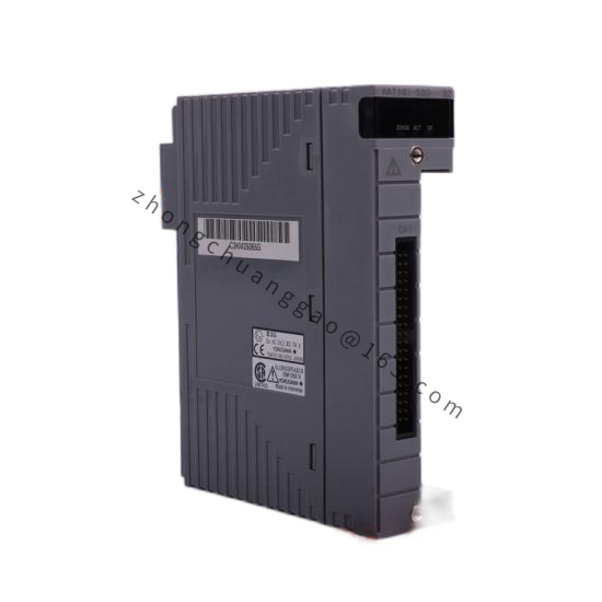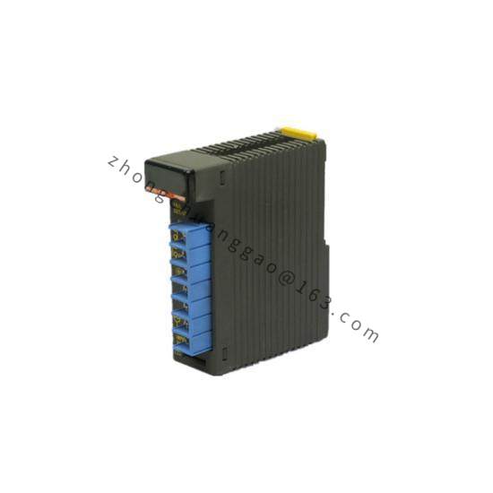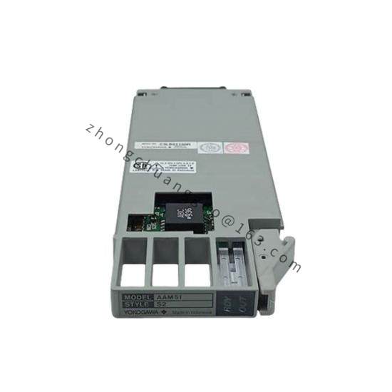

Yokogawa UR5EG3-100N-1KD-2TA-N
Product Name: Yokogawa UR5EG3-100N-1KD-2TA-N — Programmable Safety Relay (UR5 Series)
Product Introduction: The UR5EG3-100N-1KD-2TA-N is a programmable safety relay from Yokogawa’s UR5 series, designed for Safety Instrumented Systems (SIS) in accordance with IEC 61508 and IEC 61511. It provides safety monitoring and control functions with SIL 2 / SIL 3 certification capability. The model code decodes as: UR5 = Series, EG3 = Base unit, 100N = 100VAC power, 1KD = 1 forced guided contact (KY), 2TA = 2 forced guided contacts (TY), N = Normally energized configuration.
Detailed content
Technical Specifications:
- Product Series: UR5 Series Programmable Safety Relay
- Model Number: UR5EG3-100N-1KD-2TA-N
- Safety Integrity Level: SIL 2 (per IEC 61508), SIL 3 capable (with diagnostics)
- Number of Input Channels: 3 safety input channels (configurable)
- Number of Output Channels: 3 safety output channels (1KD + 2TA = 3 outputs)
- Input Type: 24 VDC (PNP/NPN selectable), 100–240 VAC/DC (universal)
- Output Type: Forced guided contacts (relay outputs)
- 1KD: 1 Normally Open (NO) + 1 Normally Closed (NC) forced guided contact
- 2TA: 2 Normally Open (NO) forced guided contacts (each with NC)
- Power Supply: 100–240 VAC/DC (100N = 100VAC nominal)
- Response Time: Less than 30 ms (typical)
- Diagnostic Coverage: Greater than 90% (for SIL 3)
- Operating Temperature: -25°C to +55°C
- Enclosure: IP20 (for control cabinet mounting)
- Dimensions: Approximately 105 × 90 × 110 mm (W×H×D)
- Weight: Approximately 0.5 kg
Functional Features:
- Programmable safety functions: E-Stop, Safety door interlock, Light curtain monitoring, Two-hand control
- Forced guided contacts ensure output state monitoring (contact welding detection)
- Cross-monitoring between output channels for fault detection
- Online testing capability (partial stroke test) without stopping the process
- Event logging with timestamp (up to 1000 events)
- LED status indicators per channel
- Test input for periodic proof testing
- Dual-channel voting for 1oo2, 2oo3 configurations
- Compact DIN-rail mount design
Performance Parameters:
- Input Voltage Range: 18–30 VDC (24VDC type), 85–264 VAC/DC (universal type)
- Input Current: Less than 5 mA (24VDC input)
- Output Contact Rating: 250VAC, 5A (resistive), 30VDC, 5A (resistive)
- Contact Material: AgNi (Silver Nickel) for high reliability
- Mechanical Life: 10,000,000 operations (minimum)
- Electrical Life: 500,000 operations (at rated load)
- Isolation Voltage: 2500V AC (input to output, input to power)
- Power Consumption: Less than 5W (typical)
- MTBF: Over 100,000 hours (at 25°C)
Material Composition:
- Housing: Flame-retardant polycarbonate (PC) — UL94 V-0 rated
- Terminal Blocks: Phoenix Contact compatible, Phosphor bronze with tin plating
- Relay Contacts: AgNi (Silver Nickel) — self-cleaning contact material
- PCB: FR-4 glass epoxy with conformal coating
- LED Indicators: High-brightness LEDs (red, green, yellow)
Structural Features:
- DIN-rail mounting (35mm EN 60715 rail)
- Front panel with LED indicators, function buttons, and test button
- Terminal blocks for all inputs, outputs, and power
- Test input terminal for external proof test signal
- Event clear button
- Reset button (manual reset type)
- Key lock (optional) for parameter protection
Working Principle: The UR5EG3 continuously monitors safety input signals (from E-stop buttons, safety door switches, light curtains, etc.) through its 3 input channels. The internal safety processor executes the programmed safety logic (AND, OR, voting, timing functions). When a safety condition is violated (e.g., E-stop pressed, safety door opened), the safety relay de-energizes all safety outputs within 30 ms, driving the forced guided contacts to their safe state. The forced guided contact design uses mechanical linkage between NO and NC contacts, so if one contact welds, the other contact’s state change is detected, triggering a diagnostic fault. The cross-monitoring function compares outputs from different channels to detect internal faults. The device performs online diagnostics including input circuit monitoring, output contact monitoring, and processor self-test. All events are logged with timestamps for incident analysis.
Advantage Highlights:
- SIL 2/SIL 3 certified — meets highest safety standards (IEC 61508/61511)
- Forced guided contacts with cross-monitoring for maximum reliability
- Online testing without process shutdown
- Programmable logic — flexible safety function implementation
- Event logging for root cause analysis
- Compact DIN-rail design — saves cabinet space
- Wide input voltage range — 24VDC or 100–240VAC/DC
- 100,000+ hour MTBF — extremely reliable
Applicable Industries:
- Oil & Gas (safety shutdown systems)
- Chemical & Petrochemical (emergency shutdown)
- Power Generation (turbine protection, boiler safety)
- Automotive Manufacturing (robot cell safety)
- Machine Building (press safety, machine guarding)
- Pharmaceutical (safety interlocks)
- Food & Beverage (safety door monitoring)
- Mining (conveyor safety, ventilation control)
Model Series:
- UR5 Series: UR5EG3 (3-channel), UR5EG5 (5-channel), UR5EG7 (7-channel)
- Power Options:
- -100N: 100VAC
- -24N: 24VDC
- -240N: 100–240VAC/DC
- Output Configurations:
- -1KD-2TA-N: 1KY + 2TY outputs, Normally energized
- -1KD-1TA-1KB-N: 1KY + 1TY + 1KB outputs
- -3TA-N: 3TY outputs
- -2KD-1TA-N: 2KY + 1TY outputs
- Reset Types:
- -N: Manual reset (latching)
- -A: Automatic reset (non-latching)
Installation Requirements:
- DIN-rail mounting: EN 60715, 35mm top-hat rail
- Ambient temperature: -25°C to +55°C
- Relative humidity: 5% to 95% RH (no condensation)
- Vibration: Within IEC 60068-2-6 limits
- Clearance: Minimum 50 mm above and below for ventilation
- Wiring: Use separate cables for safety inputs and non-safety circuits
- Grounding: Connect to protective earth (PE)
- Separation: Maintain minimum 30 mm separation from non-safety relays
Usage Precautions:
- Use only safety-rated components for safety input circuits (E-stops, switches)
- Do not bypass or defeat any safety function
- Perform proof testing at intervals specified by risk assessment (per IEC 61511)
- Do not modify safety parameters without proper risk assessment
- Replace unit immediately if diagnostic fault occurs
- Check forced guided contact operation during commissioning
- Log all events and review periodically
- Firmware updates only via Yokogawa authorized service tools
- Keep event log clear — do not allow overflow
- Verify cross-monitoring is enabled for all output channels