")
Product Introduction:
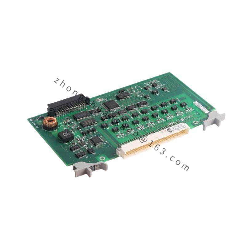
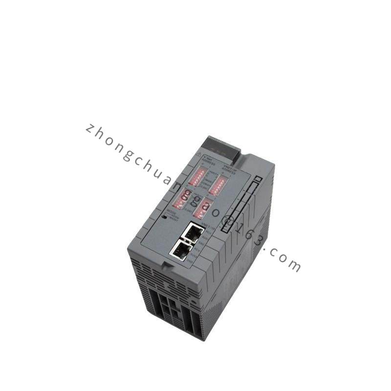
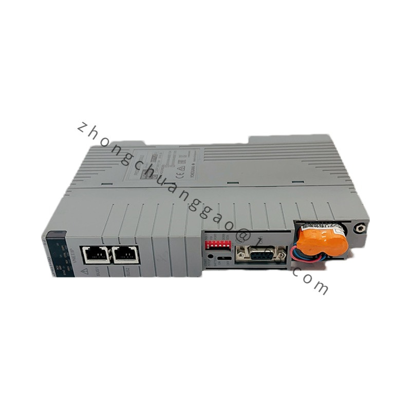
The UR1EG3-100N-6KD-2TB-N is a programmable remote I/O main unit from Yokogawa’s UR1 (Unified Remote I/O) series, part of the FA-M3 automation platform. It serves as a distributed I/O controller that aggregates field signals from remote locations and communicates with the central PLC/DCS over EtherNet/IP, Modbus TCP, or CC-Link networks. The configuration specifies: 100-point I/O capacity, 6 channels of analog input (KD), 2 terminal blocks (TB), no cover (N).
Measurement Principle:
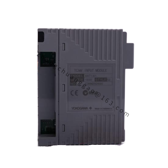
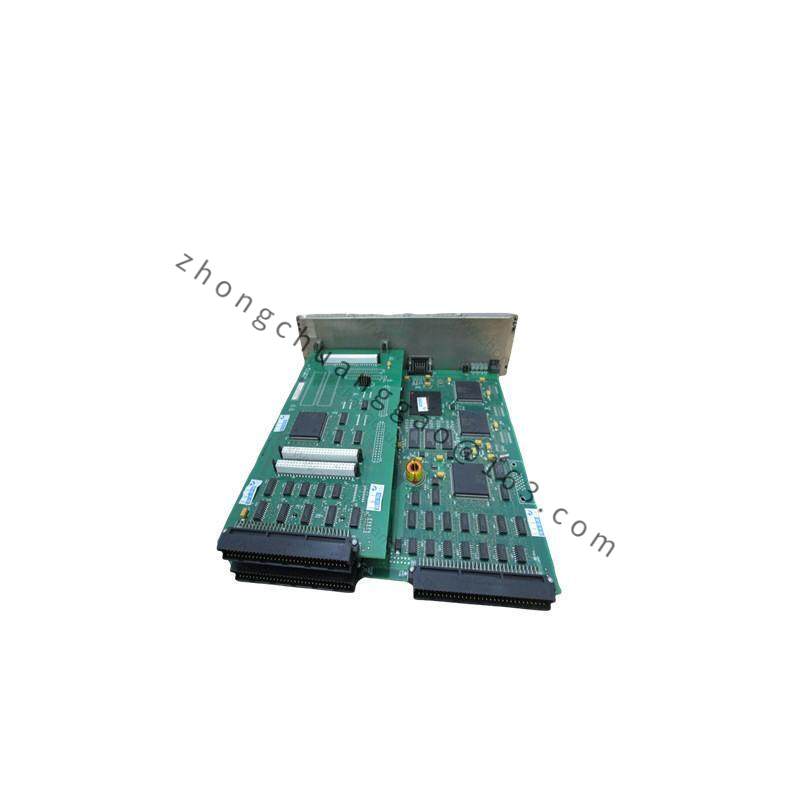
The UR1 main unit contains a high-speed backplane bus that connects to I/O modules (analog input, analog output, digital input, digital output, communication modules). Each I/O module performs A/D or D/A conversion locally, and the main unit handles protocol conversion and network communication to the host controller. The system uses cycle-based or event-driven data exchange with the central controller.
Technical Specifications:
| Parameter | Specification |
|---|---|
| Model | UR1EG3-100N-6KD-2TB-N |
| Main Unit | UR1EG3 |
| I/O Capacity | 100 Points (100N) |
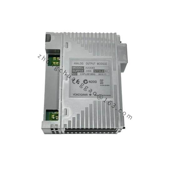
| Analog Input Modules | 6 Channels (6KD) — 4–20 mA DC / 1–5 V DC input |
| Terminal Blocks | 2 (2TB) |
| Cover | None (N) |
| Backplane Bus | High-speed serial backplane (10 Mbps) |
| Communication Protocols | EtherNet/IP, Modbus TCP, CC-Link IE Field |
| Ethernet Ports | 2 ports (RJ45, 10/100 BASE-TX) |
| Power Supply | 24 V DC (redundant input capable) |
| Power Consumption | ≤ 15 W (typical, without I/O modules) |
| Operating Temperature | 0°C to +55°C (32°F to +131°F) |
| Protection Class | IP20 (open frame, requires enclosure) |
| Dimensions (Main Unit) | Approx. 150 × 90 × 75 mm (W × H × D) |
| Mounting | DIN Rail (35 mm) or Panel Mount |
| Approvals | CE, UL, CSA, TÜV |
Structural Features:
Performance Parameters:
| Parameter | Value |
|---|---|
| Analog Input Resolution | 16-bit A/D converter |
| Analog Input Accuracy | ±0.1% of span (typical) |
| Scan Cycle (100 points) | ≤ 10 ms (typical) |
| Maximum I/O Modules | Up to 16 modules per main unit |
| Digital Input | 24 V DC, sink/source selectable |
| Digital Output | 24 V DC, transistor output, 0.5 A per point |
| Isolation | 1500 V AC (channel to channel, channel to bus) |
| MTBF | ≥ 200,000 hours (at 25°C) |
| Configuration Software | FA-M3 System Configuration Tool (Windows-based) |
Key Advantages:
Applicable Industries:
Installation Requirements:
Usage Precautions:
