

Digital guide

You are here:

Yokogawa UR1BG3-060N-C-2TA

Model Number: UR1BG3-060N-C-2TA

Product Introduction:
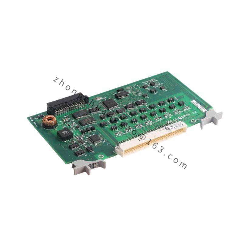
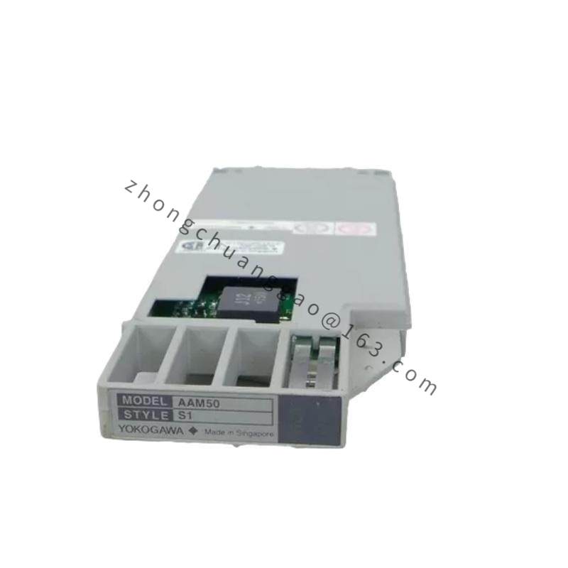
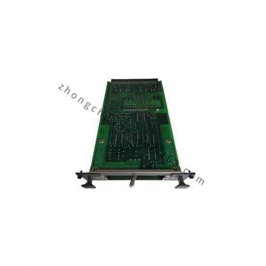
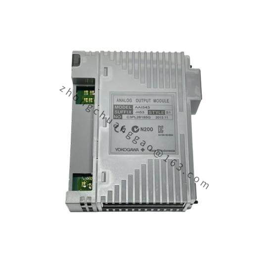
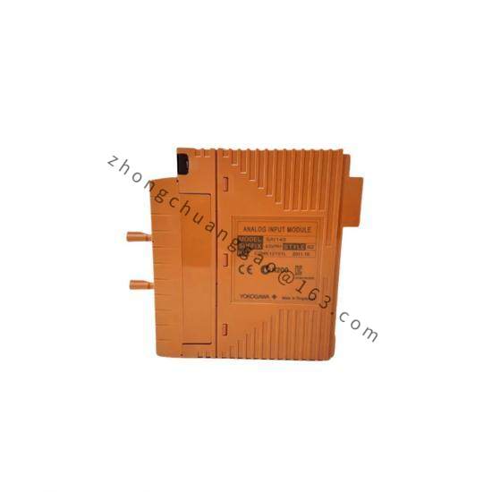
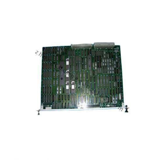
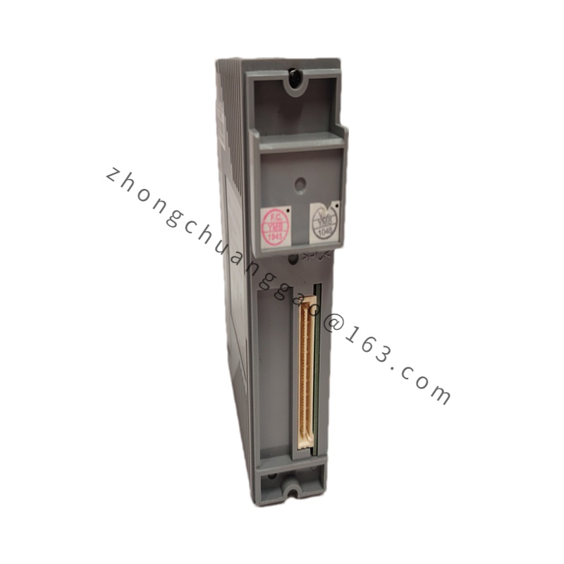
The UR1BG3-060N-C-2TA is an 8-channel universal input module from Yokogawa’s UTAdvanced series DCS system. It accepts RTD (Pt100) and Thermocouple (TC) signals and provides high-accuracy, isolated digital conversion for the UTAdvanced controller. The suffix codes indicate: 060N = Pt100 3-wire RTD inputC = channel configuration code2TA = terminal/variant code.

Detailed content

Function Features:

  • 8 input channels per module
  • RTD input: Pt100 (IEC 60751), JPt100 (JIS C1604) — 3-wire connection (060N)
  • TC input: Type K, J, T, E, R, S, B, N (configurable via software)
  • 24-bit A/D converter per channel
  • Channel-to-channel isolation: 500 V AC
  • Channel-to-bus isolation: 500 V AC
  • Cold junction compensation (CJC) for TC inputs
  • Built-in linearization for all standard TC types
  • LED per-channel status indicators

Technical Specifications:

Parameter Specification
Number of Channels 8 channels
RTD Type Pt100 (IEC 60751), JPt100 (JIS C1604)
RTD Connection 3-wire (060N)
TC Types K, J, T, E, R, S, B, N (software-configurable)
Measurement Accuracy (RTD) ±0.1°C (at 0°C), ±0.15°C (at 100°C)
Measurement Accuracy (TC) ±0.5°C (Type K), ±0.75°C (Type J)
Resolution 0.01°C (RTD), 0.1°C (TC)
A/D Resolution 24-bit
Isolation Voltage 500 V AC (channel-to-channel, channel-to-bus)
Scan Time 100 ms per channel (all 8 channels)
Power Supply 5 V DC from UTAdvanced backplane
Operating Temperature 0°C to +55°C
Dimensions (W×H×D) 32 × 120 × 160 mm
Weight Approximately 0.28 kg
Compliance Standards IEC 61010-1, CE Marking, RoHS Directive

Material Composition:

  • Housing: Flame-retardant ABS plastic (UL94 V-0)
  • Terminal blocksPhosphor bronze with gold plating
  • PCBFR-4 with conformal coating
  • Connector: UTAdvanced-compatible edge connector (64-pin)

Structure Characteristics:

  • DIN rail or backplane mounting (UTAdvanced chassis)
  • Screw-terminal blocks for each of 8 channels (16 terminals total: 3 per RTD or 2 per TC)
  • DIP switches / software configuration for input type selection
  • LED indicators per channel (green = normal, red = fault)
  • Channel group configuration via UTAdvanced engineering software

Working Principle:
Each channel contains a precision constant current source (typically 1 mA for RTD) that excites the sensor. For 3-wire RTD (060N), two wires carry the excitation current and the third wire senses the voltage across the RTD, automatically compensating for lead wire resistance (up to 10 Ω per lead). The voltage is digitized by a 24-bit delta-sigma A/D converter and transmitted to the UTAdvanced controller via the system bus (Vnet/IP). For TC inputs, the millivolt signal is measured, and cold junction compensation is applied using an internal temperature sensor. 500 V AC isolation is maintained between all channels and the system bus using optical isolators or isolation amplifiers.

Advantages & Highlights:

  • 8 channels per module reduces system cost, wiring, and panel space
  • 3-wire RTD compensation eliminates lead resistance errors — no need for 4-wire configuration
  • 24-bit resolution provides 0.01°C granularity for RTD
  • 500 V channel isolation ensures noise immunity in high-EMI environments
  • UTAdvanced compatibility enables seamless integration with CENTUM VP/CS3000 migration paths

Applicable Industries:

  • Power Generation (steam temperature, feedwater temperature)
  • Oil & Gas (wellhead monitoring, pipeline temperature)
  • Chemical Processing (reactor temperature, distillation)
  • Pharmaceutical (cleanroom temperature, lyophilizer control)
  • Food & Beverage (pasteurization, cold chain monitoring)
  • Metallurgy (furnace temperature, annealing ovens)

Installation Requirements:

  • Install in UTAdvanced DCS chassis with adequate ventilation
  • Route RTD/TC cables away from power cables (min 100 mm separation)
  • Use 3-wire shielded cable for RTD (max lead resistance 10 Ω per wire, max length 100 m)
  • Use TC-grade cable (Type K: 24 AWG chromel/alumel, max length 50 m)
  • Ground shield at controller end only (single-point grounding)
  • Torque terminal screws to 0.5 N·m (4.4 lbf·in)

Usage Precautions:

  • Verify RTD type matches module configuration (Pt100 vs JPt100 have different curves)
  • Do not apply voltage > 30 V DC to any input terminal
  • Do not disconnect TC while module is energized (SBA alarm will trigger)
  • Maximum 3-wire lead resistance: 10 Ω per wire (exceeding this causes measurement error)
  • Re-calibrate annually for SIL-rated or safety-critical applications
  • Do not mix RTD and TC on the same channel — configure all 8 channels as one type per module

You may also like