

Digital guide

You are here:

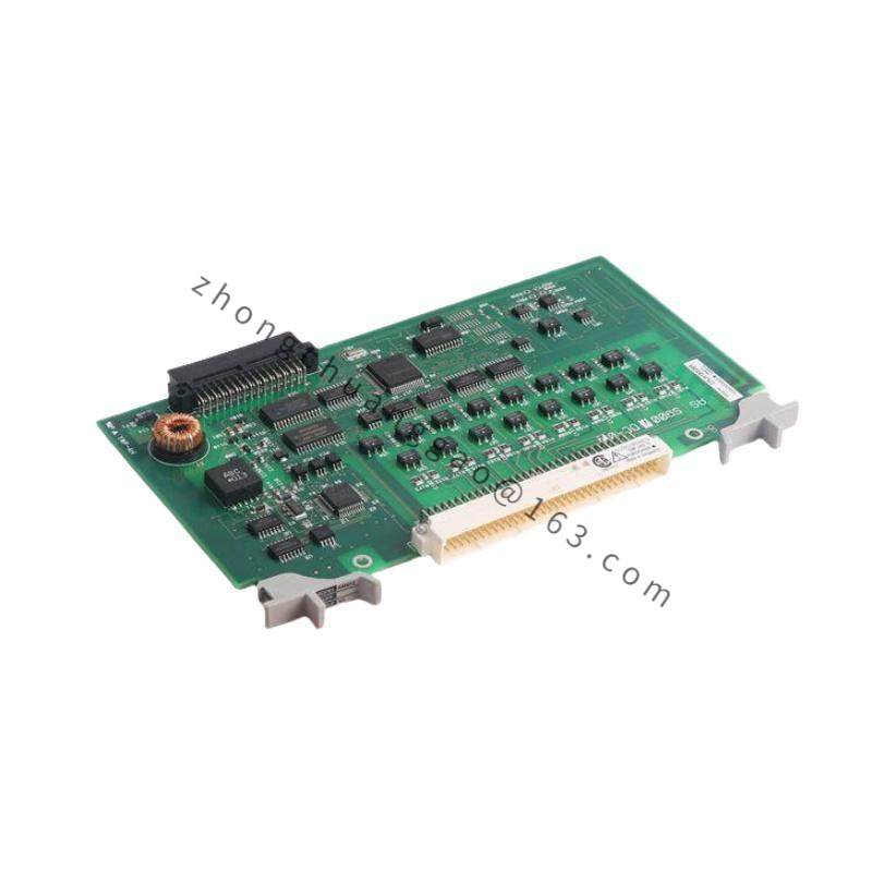
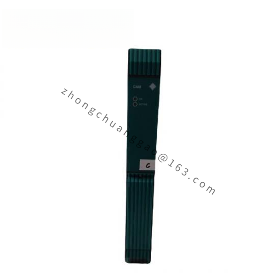
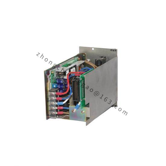
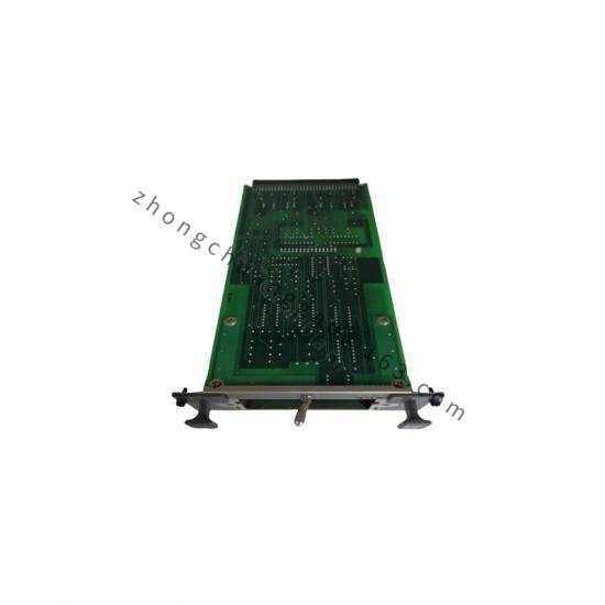
YOKOGAWA UD1B-045N-1K1X1-2

Product Introduction:
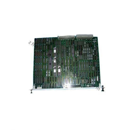
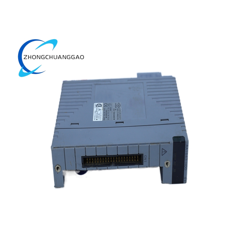
The UD1B-045N-1K1X1-2 is a 400W-class AC servo drive from Yokogawa’s UD1B series. It is designed to drive AC servo motors for high-precision motion control applications. The model code breakdown is: UD1B = Series / 045 = 400W rated output / N = Normal duty / 1K1 = Single-phase 200V input / X1 = Specific option code / 2 = Revision level. This drive provides position, speed, and torque control with high-speed communication capabilities.

Detailed content

Technical Specifications:

  • Rated Output Power400 W (0.4 kW)
  • Rated Output Current2.0 A (continuous)
  • Peak Output Current: 6.0 A (3 seconds)
  • Input VoltageSingle-phase 200–240 VAC (1K1 option) / Three-phase 200–240 VAC available in other variants
  • Input Frequency50/60 Hz ± 5%
  • Output Frequency: 0–3 kHz (sine wave PWM)
  • Control ModePosition control, Speed control, Torque control, Speed/Torque switchable
  • Position Resolution: 131,072 pulses per revolution (electronic gear)
  • Speed Loop Bandwidth1.5 kHz (typical)
  • Position Loop Bandwidth: 500 Hz (typical)
  • Communication: MECHATROLINK-II, MECHATROLINK-III, EtherCAT, Profibus, Modbus (optional board)
  • Power Supply: 200–240 VAC single-phase (1K1) / 200–240 VAC three-phase (3K1)
  • Power ConsumptionApproximately 600 VA (rated output)
  • Operating Temperature0 to +40 °C (32 to 104 °F) — derating above 35°C
  • Cooling Method: Forced air cooling (built-in fan)
  • Protection RatingIP20 (when mounted in control panel)
  • DimensionsW 65 mm × H 175 mm × D 210 mm (approximate, excluding connectors)
  • WeightApproximately 1.8 kg

Functional Features:

  • Auto-tuning — inertia identification, rigidity tuning, vibration suppression
  • Electronic gear function — position control with flexible gear ratios
  • JOG operation, return-to-home, absolute position backup
  • Online tuning — parameters adjustable during operation
  • Built-in braking resistor (external resistor optional for high-inertia loads)
  • Fault history recording — up to 8 recent faults stored
  • Safety functions: Overcurrent, overvoltage, undervoltage, overtemperature, encoder error, position deviation alarm

Performance Parameters:

  • Speed Control Accuracy: ±0.01% (at rated speed, no load)
  • Positioning Accuracy: ±1 pulse (with absolute encoder, 131,072 pulses/rev)
  • Speed Response: 90% of rated speed in ≤ 20 ms
  • Torque Response: 90% of rated torque in ≤ 5 ms
  • Regenerative Braking: Built-in dynamic brake (75% rated torque)

Structural Features:

  • HousingAluminum die-cast with epoxy coating (corrosion resistant)
  • ConnectorsMotor power connector (U, V, W), encoder connector (A, B, Z, +5V), control I/O connector (CN1, CN2), communication connector (RJ-45 for EtherCAT, D-sub for MECHATROLINK)
  • Terminal Block: Screw terminal for power and I/O signals (wire size 0.5–2.5 mm²)
  • Mounting: DIN rail or panel mounting with screws
  • Cooling Fan: Built-in 40 mm × 40 mm fan, 24 VDC

Applicable Industries:

  • Semiconductor Manufacturing — Wafer stage positioning, pick-and-place
  • Electronics Assembly — SMT feeder control, precision indexing
  • Machine Tools — CNC axis drive, spindle control
  • Printing & Packaging — Register control, cut-to-length
  • Robotics — Joint axis servo control

Installation Requirements:

  • Mount in a ventilated enclosure with minimum 100 mm clearance on all sides
  • Use shielded cable for encoder signals (maximum 10 m for differential, 5 m for single-ended)
  • Connect motor power cable (U, V, W) with proper phase sequence
  • Connect grounding terminal to panel earth (resistance ≤ 100 Ω)
  • Install EMC filter on input power line (recommended for industrial environments)
  • Maximum motor cable length: 50 m (with output filter installed)

Precautions:

  • Do not operate the drive with the front cover removed — high voltage present
  • Do not exceed rated output current — will trigger overcurrent fault and may damage IGBT modules
  • Ensure proper phase sequence on motor power connection — reverse rotation will occur with wrong sequence
  • Use Yokogawa-approved servo motor — mismatched motor will cause tuning failure
  • Perform auto-tuning after every mechanical change (coupling, load change, gear ratio change)
  • Replace cooling fan every 30,000 hours or when noise increases

You may also like