
Digital guide

You are here:

YOKOGAWA SPW482-E3

Product Introduction:
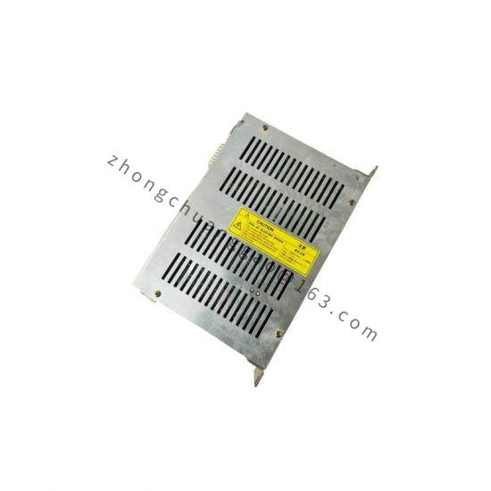
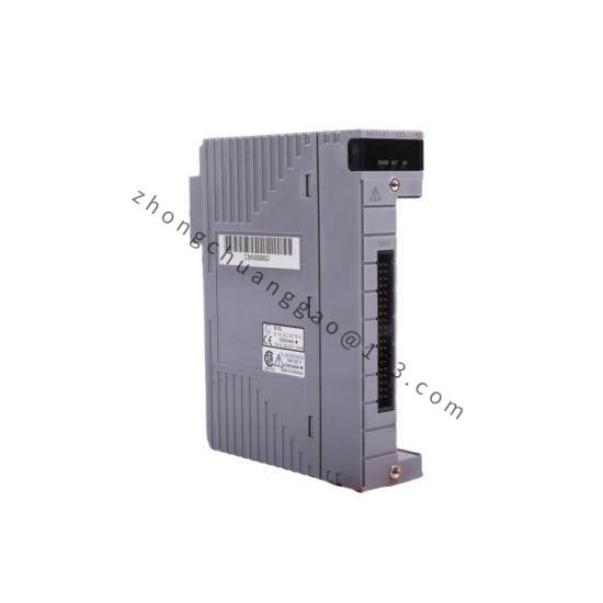
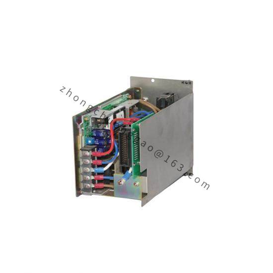
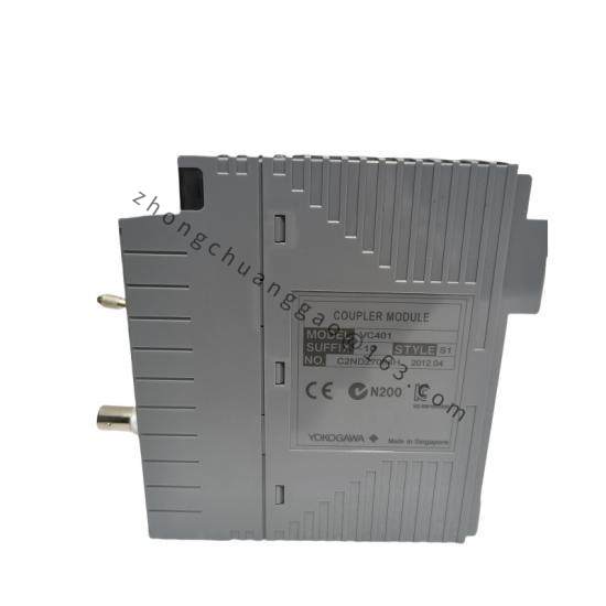
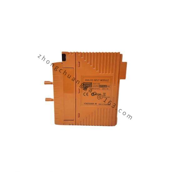
The SPW482-E3 is a 2-channel signal isolator/repeater from Yokogawa’s SPW482 series. It accepts a 4–20mA DC input signal and provides an isolated 4–20mA DC output signal. The E3 suffix indicates the specific model variant (output configuration and power options). This device is used to isolate, transmit, and condition analog signals between field instruments and control systems, eliminating ground loops and noise.

Detailed content

Technical Specifications:

  • Number of Channels2 channels (independent, isolated)
  • Input Signal4–20mA DC (2-wire powered)
  • Output Signal4–20mA DC (2-wire powered, isolated)
  • Isolation Voltage: 1500 VAC (1 minute) between input, output, and power supply
  • Power Supply24 VDC (2-wire loop-powered from input signal)
  • Accuracy: ±0.1% of span (typical)
  • Temperature Drift±0.01% of span per °C
  • Response Time: ≤ 100 ms (0–90% step response)
  • Load Resistance: Maximum 600 Ω (at 24 VDC supply)
  • Operating Temperature-10 to +60 °C (14 to 140 °F)
  • Protection RatingIP20 (screw terminal cover provides IP40 when installed)
  • Dimensions22.5 mm (W) × 115 mm (H) × 115 mm (D) (DIN rail mount: 35 mm rail)
  • Weight: Approximately 0.1 kg per channel

Functional Features:

  • Galvanic isolation between input and output (eliminates ground loops)
  • Signal conversion — input 4–20mA → isolated output 4–20mA (1:1 ratio)
  • 2-wire loop power — no external power supply required
  • Linearity correction — ensures accurate signal transmission
  • Fault detection — output dropout alarm (configurable)
  • DIN rail mounting — compact, space-saving installation

Performance Parameters:

  • Input Impedance: 250 Ω (typical, at 24 VDC)
  • Output ImpedanceHigh impedance current source
  • Insulation Resistance≥ 100 MΩ at 500 VDC
  • Dielectric Strength: 1500 VAC, 50/60 Hz, 1 minute
  • Long-Term Stability: ±0.2% of span per year

Structural Features:

  • Housing: Flame-retardant polycarbonate (UL94 V-0)
  • TerminalsScrew terminal, wire size 0.5–2.5 mm² (AWG 20–14)
  • MountingDIN rail 35 mm (EN 60715)
  • Indicator LED: Green LED for normal operation, Red LED for fault/alarm

Applicable Industries:

  • Oil & Gas — Signal isolation for transmitters in hazardous areas
  • Chemical Plants — Ground loop elimination in distributed control systems
  • Power Plants — Current signal transmission from remote sensors
  • Water Treatment — Isolated signal transmission for level/flow transmitters
  • Manufacturing — Analog signal conditioning for PLC/DCS inputs

Installation Requirements:

  • Mount on DIN rail 35 mm (EN 60715)
  • Connect input loop: 24 VDC (+) → Transmitter (+) → SPW482 Input (+) → SPW482 Input (-) → 24 VDC (-)
  • Connect output loop: 24 VDC (+) → SPW482 Output (+) → Receiving Device Input (+) → Receiving Device Input (-) → SPW482 Output (-) → 24 VDC (-)
  • Maximum cable length: 500 m (shielded twisted pair recommended)

Precautions:

  • Do not exceed 28 VDC on any terminal
  • Do not apply voltage between input and output terminals — isolation will be damaged
  • Ensure correct polarity for all connections (reverse polarity will damage the device)
  • Do not open the housing — no user-serviceable parts inside

You may also like