
Product Introduction:
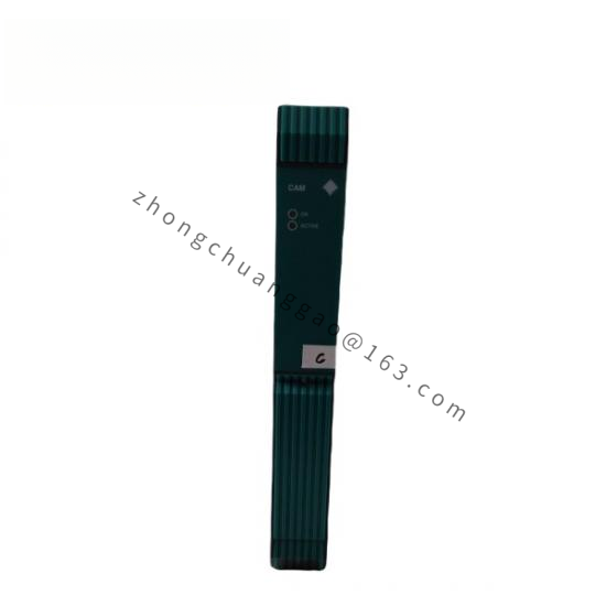
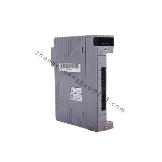
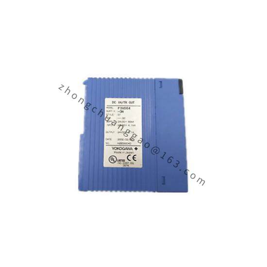
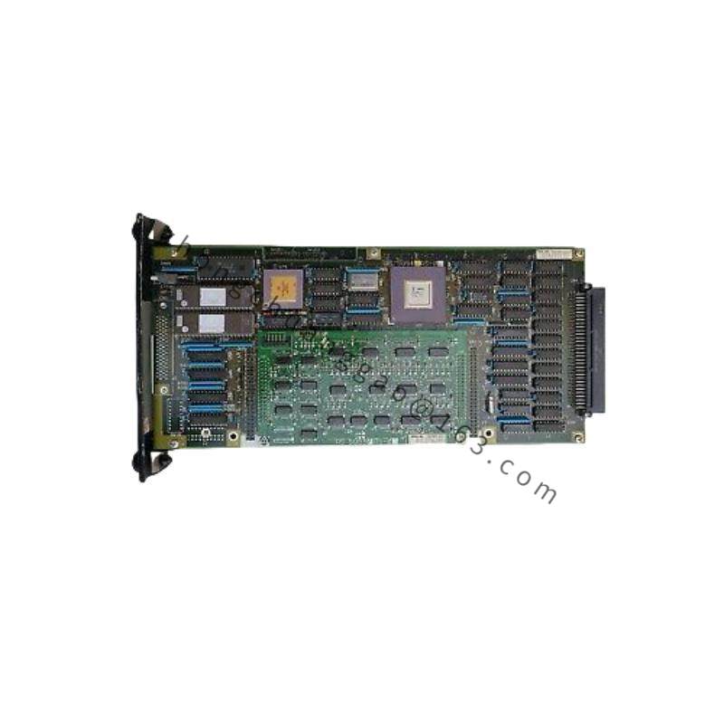
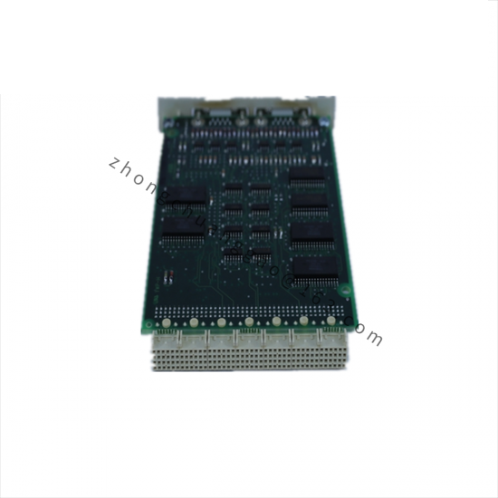
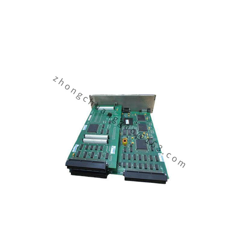
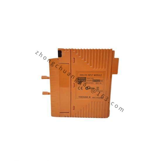
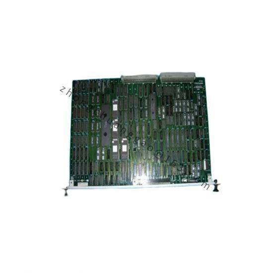
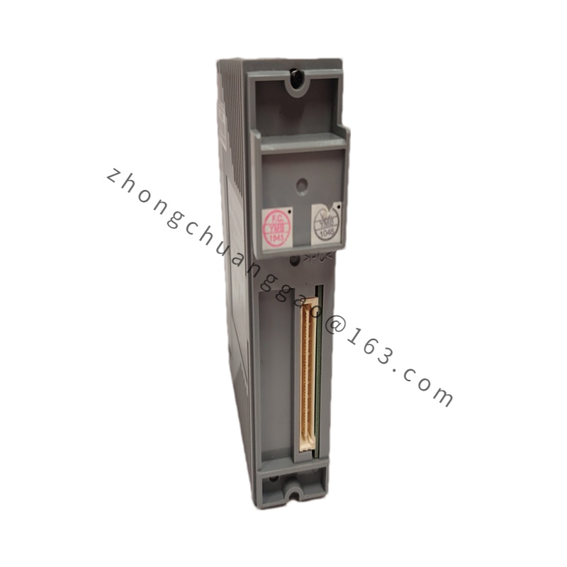
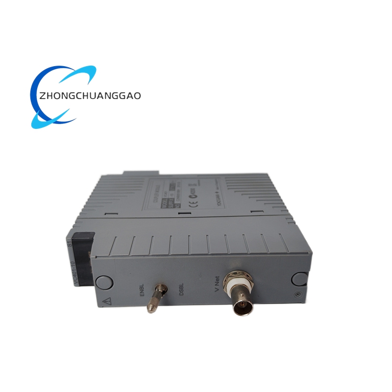
The SDV551-P10 is a smart digital valve controller designed to operate pneumatic control valves (globe, butterfly, ball valves) with high precision. It accepts a 4-20 mA control signal from a DCS/PLC and converts it to a proportional pneumatic output signal to the valve actuator. The P10 suffix defines the specific input/output range and diagnostic configuration.
Working Principle:
The SDV551 receives a 4-20 mA DC setpoint signal from the control system. An internal microprocessor compares the setpoint to the actual valve stroke position (measured by a built-in LVDT sensor or external feedback). The controller drives an internal I/P (current-to-pneumatic) converter to generate a proportional air pressure (3-15 psi or 0.2-1.0 bar) to the valve actuator, positioning the valve to match the setpoint. HART communication enables remote configuration, diagnostics, and stroke calibration.
Technical Specifications:
| Parameter | Value |
|---|---|
| Input Signal | 4-20 mA DC (2-wire) |
| Output Signal | 4-20 mA DC to valve positioner OR 3-15 psi (0.2-1.0 bar) pneumatic |
| Stroke Monitoring | Built-in LVDT — 0-100% stroke measurement, ±1% accuracy |
| Communication | HART 7 |
| Power Supply | 24 V DC (loop powered) or 100-240 V AC |
| Air Supply | 1.4-7.0 bar (20-100 psi), clean and dry |
| Ambient Temperature | -20°C to +70°C |
| Protection Rating | IP65 / IP66 (NEMA 4X) |
| Ex Rating | Ex ia IIC T4 Ga / Ex d IIC T6 Gb |
| SIL Rating | SIL 2 (per IEC 61508) |
| Response Time | ≤ 1 second (full stroke) |
| Diagnostics | Stroke monitor, air supply pressure monitor, solenoid valve monitor, travel limit alarm |
| Mounting | Wall mount or pipe mount (DIN clip optional) |
Material Composition:
Advantages:
Applicable Industries:
Oil and gas, chemical and petrochemical, power generation, pulp and paper, water treatment, mining, pharmaceutical
Installation Requirements:
Usage Notes: