
Digital guide

You are here:

Yokogawa SDV144-S33

Model Number: SDV144-S33

Product Introduction:
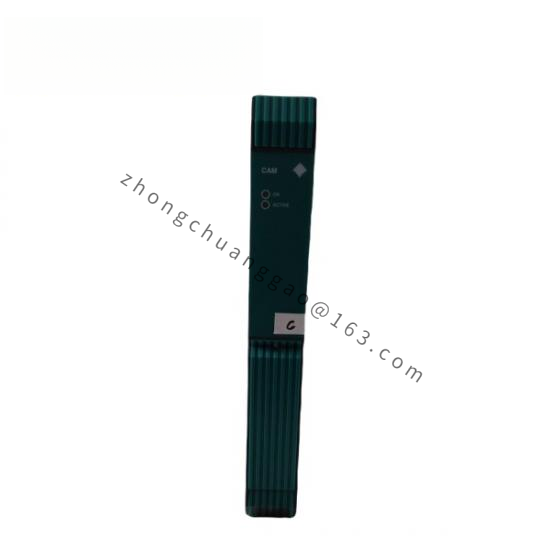
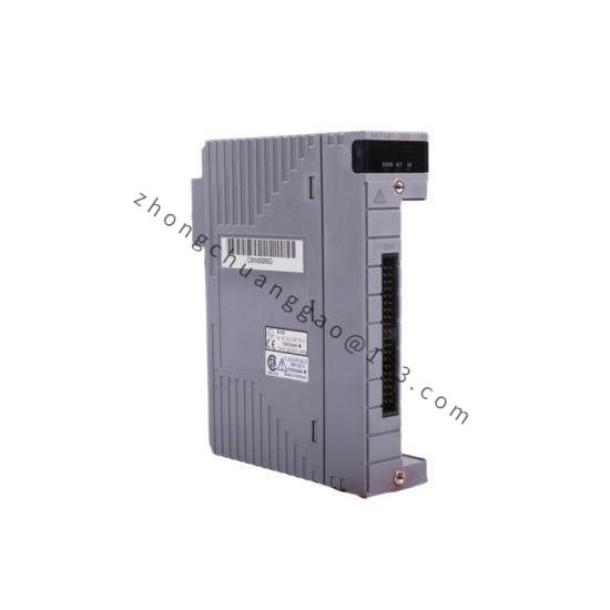
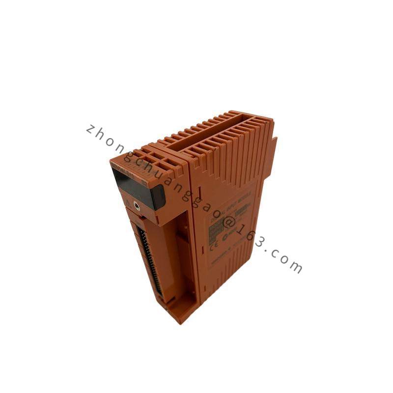
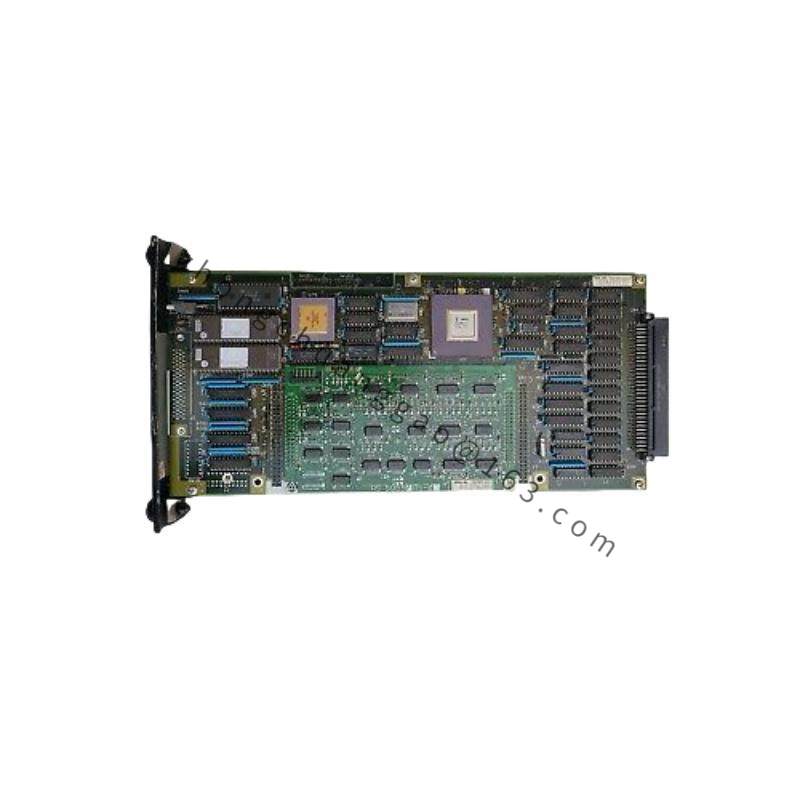
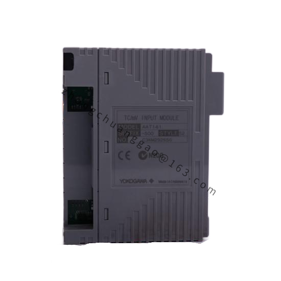
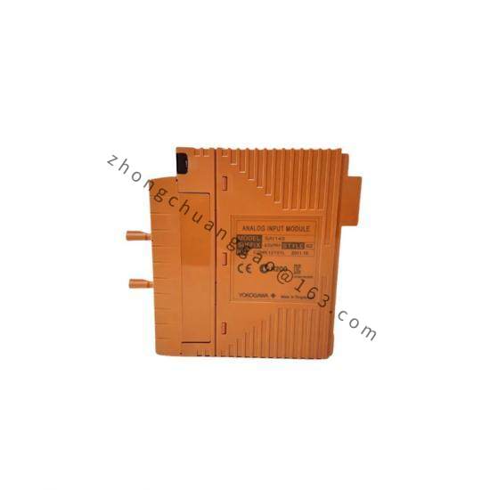
The Yokogawa SDV144-S33 is an 8-channel digital input/output module designed for the Yokogawa FA-M3 distributed control system. The S33 suffix indicates relay output type. This module provides 8 channels of discrete (on/off) signal interfacing between field devices (switches, relays, solenoids, indicators) and the FA-M3 central processor. It is used for discrete control, status monitoring, and interlocking applications.

Detailed content

Technical Specifications:

  • Number of Channels: 8 channels (digital I/O)
  • Input Type: Dry contact (volt-free contact), 24 V DC (sink/source selectable)
  • Output Type: Relay output (SPDT) — indicated by “S33”
  • Input Voltage: 24 V DC (sink or source)
  • Input Current: 5 mA (typical)
  • Output Contact Rating: 2 A at 250 V AC (resistive), 30 V DC (resistive)
  • Output Type: SPDT (Single Pole Double Throw) relay
  • Response Time: 10 ms (input to output, typ.)
  • Isolation: 500 V AC between channels, 500 V AC channel to backplane
  • Power Consumption: 3.5 W (typical)
  • Operating Temperature: 0 to 55 °C (32 to 131 °F)
  • Humidity: 5 to 95% RH (non-condensing)
  • Mounting: DIN rail or direct mounting in FA-M3 rack
  • Dimensions: 25 × 90 × 130 mm (W × H × D) approximately
  • Weight: Approximately 150 g (0.33 lb)

Functional Features:

  • 8 Discrete Channels: Independently configurable as input or output per channel
  • Dry Contact Input: Compatible with volt-free contacts from field switches, limit switches, and proximity sensors
  • Relay Output: SPDT relay suitable for driving solenoid valves, indicator lamps, and small motors
  • LED Indicators: Per-channel LED for input status (green) and output status (red)
  • Online Configuration: Channel direction (input/output) configurable via FA-M3 programming software
  • Fail-Safe Option: Output default state (ON/OFF) configurable for safety applications
  • Short Circuit Protection: Built-in protection on all input channels

Performance Parameters:

  • Insulation Resistance: 100 MΩ minimum at 500 V DC
  • Dielectric Strength: 1500 V AC for 1 minute (input to output, input to backplane)
  • Common Mode Rejection: 120 dB minimum at 50/60 Hz
  • Backplane Communication: FA-M3 high-speed serial bus
  • Update Rate: 10 ms (all 8 channels)
  • MTBF: 100,000 hours (minimum)

Structural Features:

  • FA-M3 standard module format
  • Front-facing LED indicators per channel (8 green for input, 8 red for output)
  • Front-facing terminal blocks for field wiring (screw terminals)
  • Rear-facing backplane connector for FA-M3 bus connection
  • DIN rail clip or screw mounting option
  • Module identification label on front face

Working Principle:
The SDV144 module interfaces discrete field signals with the FA-M3 central processor via the backplane bus. For input channels: field dry contacts or 24 V DC signals are connected to the input terminals. The input circuit conditions the signal (filters, debounces) and sends the digital state (ON/OFF) to the FA-M3 processor. For output channels: the FA-M3 processor sends a digital command to the module, which energizes or de-energizes the corresponding SPDT relay. The relay contacts switch the external load (solenoid, lamp, etc.). All 8 channels are scanned every 10 ms.

Advantage Highlights:

  • 8 Channels in One Module: Reduces rack space and wiring compared to individual I/O modules
  • Relay Output: SPDT contacts provide both NO and NC switching for versatile control
  • Dry Contact Compatibility: Works with any field switch regardless of voltage
  • FA-M3 Integration: Seamless integration with Yokogawa FA-M3 DCS platform
  • Per-Channel LEDs: Instant visual status indication for troubleshooting
  • Online Reconfiguration: Change input/output assignment without removing the module

Applicable Industries:

  • Oil refineries (pump status, valve position, alarm indication)
  • Chemical plants (interlock systems, status monitoring)
  • Power plants (breaker status, turbine auxiliary systems)
  • Water treatment (pump control, valve position)
  • Manufacturing (conveyor status, machine interlocks)
  • Building automation (damper position, fire alarm interface)

Installation Requirements:

  • Install in FA-M3 compatible rack or DIN rail enclosure
  • Ensure ambient temperature remains within 0 to 55 °C
  • Use 22–16 AWG wire for field connections (dry contact inputs)
  • Use 22–14 AWG wire for relay output connections (up to 2 A)
  • Maintain minimum 50 mm clearance between modules for airflow
  • Ground the module chassis to plant earth
  • Label all field wiring per I/O list for maintenance clarity

Usage Precautions:

  • Do not exceed 2 A at 250 V AC or 30 V DC on any relay output channel
  • Verify input type (sink vs. source) matches field device wiring before energizing
  • Use flyback diodes across DC solenoid loads to suppress relay contact arcing
  • Replace the entire module if any channel shows persistent failure (not field-repairable)
  • Ensure backplane connector is fully seated before applying power
  • Do not mix AC and DC loads on the same relay channel

You may also like