

Digital guide

You are here:

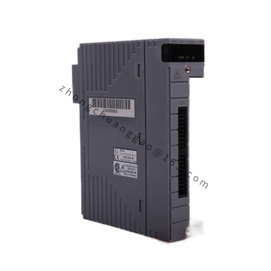
YOKOGAWA SD10ZZZSD10ZZZ04

Manufacturer: Yokogawa Electric Corporation

Description:
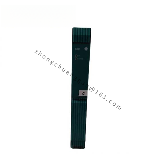
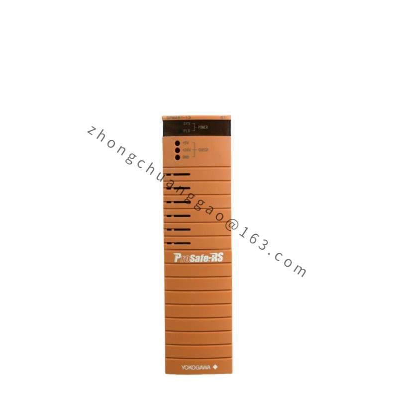
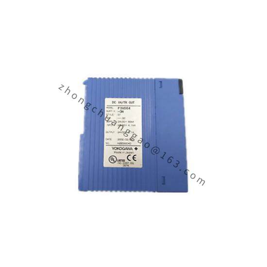
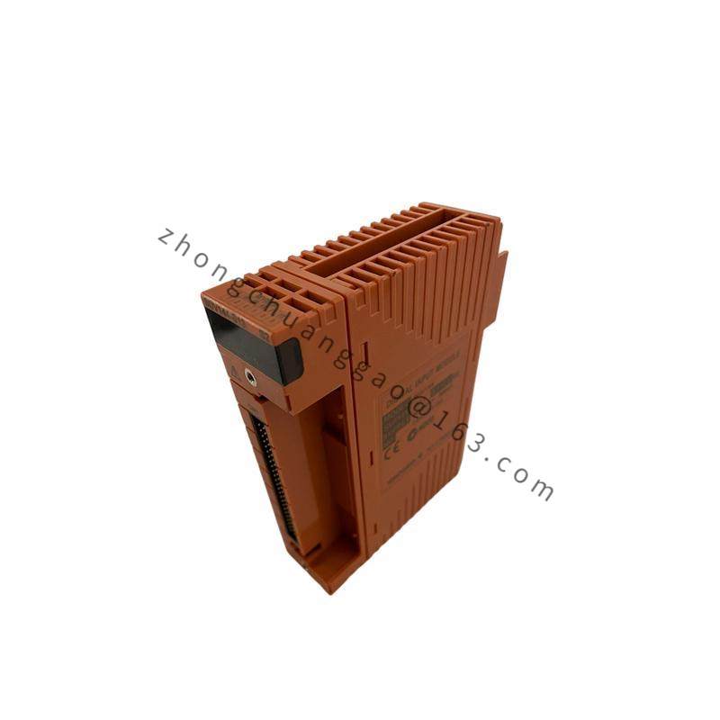
The SD10ZZZSD10ZZZ04 is a 4-channel signal distributor/isolator from the SD10 series. The “04” indicates 4 channels. The “ZZZ” fields denote the standard configuration for 4–20 mA DC input and output with channel-to-channel isolation. It is used to distribute a single analog signal to multiple destinations or to isolate signals between different system segments to eliminate ground loops.

Detailed content

Technical Specifications:

  • Number of Channels4 channels
  • Input Signal: 4–20 mA DC (2-wire)
  • Output Signal4–20 mA DC (2-wire, isolated per channel)
  • Isolation: Channel-to-channel galvanic isolation (500 V DC)
  • Input-to-Output Isolation500 V DC
  • Accuracy±0.1% of Span (FS)
  • Load Resistance: Maximum 600 Ω per output (at 24 V DC supply)
  • Power Supply: 24 V DC (bus-powered or loop-powered)
  • Power Consumption: Maximum 1.5 W per module
  • Operating Temperature: 0°C to +50°C (+32°F to +122°F)
  • Protection RatingIP20 (cabinet mounting only)
  • Dimensions (W × H × D)25 mm × 160 mm × 115 mm (card format, DIN rail mount)
  • WeightApproximately 0.3 kg

Functional Features:

  • 4 independent isolated outputs from a single input signal
  • Channel-to-channel isolation — each output is electrically independent
  • Signal distribution — one input can drive up to 4 separate destinations
  • Ground loop elimination — isolation breaks unwanted current paths
  • Signal buffering — maintains signal integrity over long cable runs
  • LED indicators per channel for input/output status
  • DIN rail mounting for easy cabinet installation

Structural Characteristics:

  • Card-type module for DIN rail mounting (TS 35/7.5 or TS 35/15)
  • Plastic housing with terminal blocks on front panel
  • LED status indicators per channel (green = normal, red = fault)
  • Screw-terminal connections for all inputs and outputs

Working Principle:
The SD10 accepts a 4–20 mA DC input signal on its input terminal. An internal isolation amplifier converts the current signal to a voltage, passes it through a high-voltage isolation barrier (500 V DC) using opto-couplers or transformers, and reconverts it to a 4–20 mA DC output on each of the 4 isolated output channels. Each output channel is completely independent, allowing the same signal to be sent to 4 different devices (e.g., DCS, recorder, indicator, PLC) without ground loop interference.

Advantages:

  • Eliminates ground loops — the primary reason for using signal isolators
  • 4 outputs from 1 input — reduces wiring and transmitter count
  • ±0.1% accuracy — signal quality is maintained across all outputs
  • Compact DIN rail design — saves cabinet space
  • No external power required — loop-powered operation

Applicable Industries:

  • Oil and Gas
  • Chemical Processing
  • Power Generation
  • Water and Wastewater
  • Building Automation (HVAC)

Installation Requirements:

  • Mount on DIN rail inside a control cabinet
  • Connect the input signal wires to the input terminal block
  • Connect each output to its destination device using shielded twisted-pair cable
  • Ensure each output loop has its own power supply or is loop-powered
  • Ground the module chassis to the cabinet ground bar

Precautions:

  • Do not connect voltage signals (0–10V) to the current input — this will damage the module
  • Maximum input current: 25 mA DC (do not exceed)
  • Ensure the total load on all 4 outputs does not exceed the input transmitter’s drive capability (typically 600 Ω per output)
  • Do not mix hazardous area and non-hazardous area wiring on the same module unless properly rated

You may also like