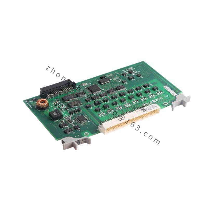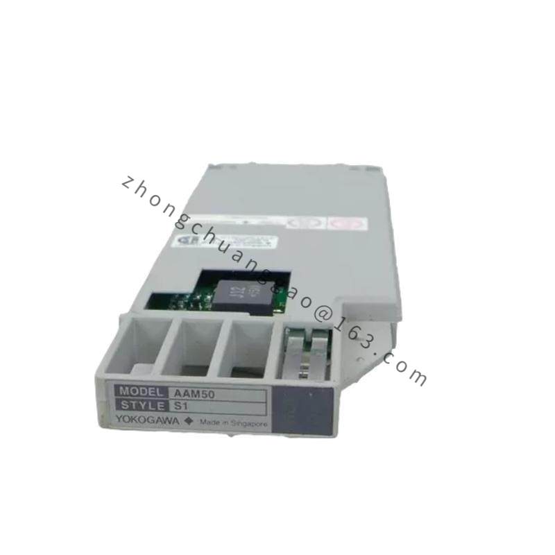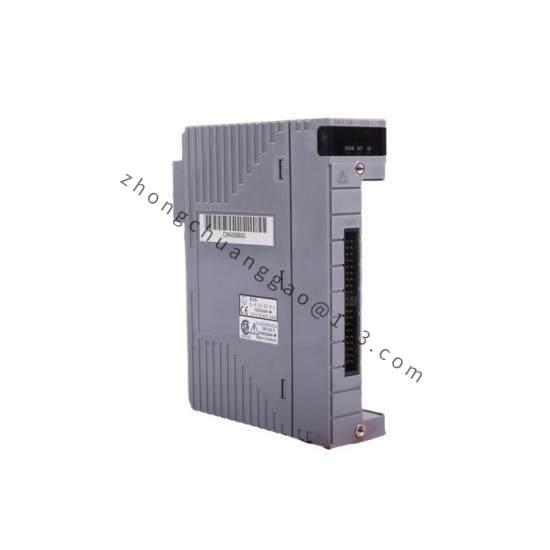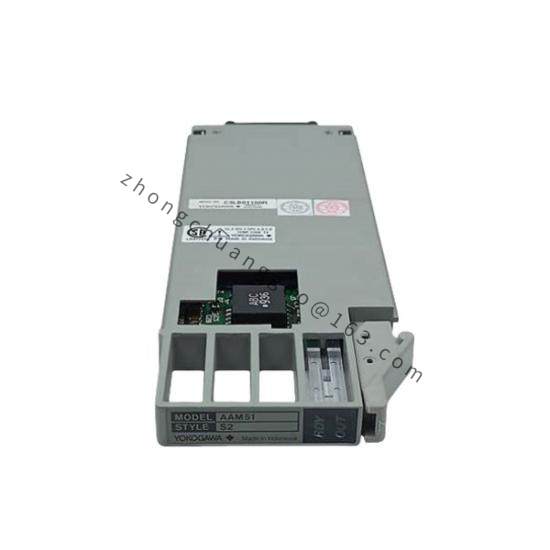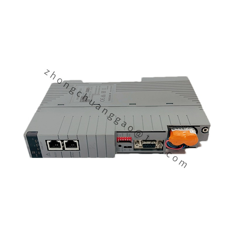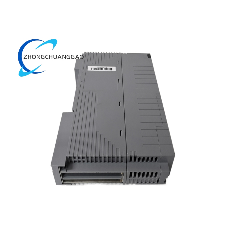

YOKOGAWA NFDV161-P50-NFDV1
Product Introduction:
The NFDV161-P50-NFDV1 is a digital vortex flowmeter from Yokogawa’s NFDV160 series. The NFDV161 indicates the transmitter model. The P50 specifies the vortex shedder (sensor) size: P50 = 50 mm nominal pipe size (DN50, 2-inch). The NFDV1 at the end confirms the converter/transmitter model. This flowmeter measures volumetric flow rate of liquids, gases, and steam using the vortex shedding principle.
Detailed content
Technical Specifications:
| Parameter | Value |
|---|---|
| Flowmeter Type | Digital Vortex Flowmeter (Vortex Shedding Principle) |
| Transmitter Model | NFDV161 |
| Sensor Size | P50 = DN50 (2-inch, 50 mm nominal bore) |
| Converter Model | NFDV1 |
| Pipe Size Range | DN15 to DN300 (1/2″ to 12″) — P50 = DN50 |
| Fluid Types | Liquids, Gases, Steam (saturated and superheated) |
| Flow Rate Range (Water) | 1.5 to 75 m³/h (DN50, P50) |
| Flow Rate Range (Steam) | 4 to 250 kg/h (DN50, P50, saturated steam at 0.7 MPa) |
| Accuracy (Liquid) | ±1.0% of reading (Re ≥ 20,000) |
| Accuracy (Gas/Steam) | ±1.5% of reading (Re ≥ 20,000) |
| Repeatability | ±0.2% of reading |
| Output Signal | 4–20 mA DC (pulse + 4–20 mA) / HART 7 / Pulse output (open collector) |
| Power Supply | 24 V DC (12–36 V DC range) or 100–240 V AC |
| Operating Temperature (Fluid) | -40°C to +250°C (depends on wetted materials) |
| Operating Temperature (Electronics) | -20°C to +60°C |
| Pressure Rating | PN16 / PN25 / PN40 / Class 150 / Class 300 (configurable) |
| Protection Rating (Transmitter) | IP67 (NEMA 4X) |
| Wetted Materials | SUS316L Stainless Steel (standard) |
| Communication | HART 7 protocol |
| Display | Local LCD on converter (NFDV1) — flow rate, totalizer, diagnostics |
| Process Connection | Wafer type (JIS 10K/20K) or Flange (JIS 10K/20K/40K, ANSI 150/300, DIN PN16/25/40) |
| Straight Pipe Requirement | Upstream: 15D, Downstream: 5D (minimum) |
| Model Code NFDV161 | NFDV160 series transmitter, integrated converter type |
| Model Code P50 | Sensor nominal size: DN50 (2″) |
| Model Code NFDV1 | Converter with HART, 4–20 mA, pulse output |
Functional Features:
- Digital signal processing (DSP) — advanced filtering eliminates vibration and noise interference
- Auto-sensing of fluid type — detects liquid, gas, or steam automatically
- Density compensation for steam — built-in steam table for mass flow calculation
- Totalizer function — displays instantaneous flow, total flow, and flow rate
- Self-diagnostics — sensor blockage detection, signal quality monitoring, electronics health check
- HART 7 communication — remote configuration, calibration, and diagnostics via HART communicator
- Low flow cut-off — configurable minimum flow threshold below which output = 4 mA (not zero)
Material Composition:
- Shedder Bar (Bluff Body): SUS316L Stainless Steel — precision-machined, T-shape or trapezoidal profile
- Sensor Housing: SUS316L Stainless Steel (cast or forged)
- Piezoelectric Sensor: Lead Zirconate Titanate (PZT) ceramic element
- Transmitter Housing (NFDV1): Aluminum die-cast, epoxy-coated, IP67
- Process Seal: Viton O-ring (standard), Kalrez available for high-temp
- Cable Gland: SUS316L stainless steel, PG11 or 1/2″ NPT
Structural Features:
- Wafer-style sensor — clamps between pipe flanges with gaskets
- Integral transmitter (NFDV1) — mounted directly on sensor body, no separate junction box
- Local LCD display — visible through polycarbonate window on transmitter head
- Cable entry: top or side entry (rotatable conduit fitting)
- Compact design — total length: approx. 200 mm (DN50)
Working Principle:
When fluid flows past the bluff body (shedder bar), vortices are shed alternately from each side, creating a Kármán vortex street. The frequency of vortex shedding (f) is directly proportional to flow velocity (v): f = St × v / d, where St = Strouhal number (≈ 0.17 for Re > 20,000) and d = shedder bar width. The piezoelectric sensor detects the pressure oscillations caused by the vortices and converts them to an electrical signal. The DSP in the NFDV1 converter processes the signal, applies temperature/pressure compensation, and outputs a 4–20 mA signal proportional to flow rate. For steam, the converter uses built-in IAPWS steam tables to calculate mass flow from volumetric flow and density.
Advantages & Highlights:
- No moving parts — zero maintenance, infinite sensor life
- Wide turndown ratio: 10:1 to 50:1 — accurate at low and high flows
- SUS316L wetted parts — suitable for corrosive, high-purity, and sanitary applications
- HART communication — configure and calibrate from control room
- Steam mass flow — built-in density compensation, no separate temperature/pressure transmitter needed
- Compact integral design — no remote transmitter, no signal degradation
Applicable Industries:
- Steam Flow Measurement (boiler, heat exchanger, condensate return)
- Natural Gas Flow (custody transfer, fuel gas monitoring)
- Chemical Processing (acid, solvent, slurry flow)
- Power Generation (feedwater, cooling water, steam) —
- Food & Beverage (water, juice, milk flow — sanitary flange option available)
- HVAC (chilled water, hot water flow)
Installation Requirements:
- Upstream straight pipe: ≥ 15D (750 mm for DN50)
- Downstream straight pipe: ≥ 5D (250 mm for DN50)
- Do not install near pumps, valves, or elbows — causes flow profile distortion
- Mount transmitter vertically or horizontally — avoid mounting on top of pipe (condensate accumulation)
- For steam: install condensate pot if mounting above pipe
- Ground the transmitter to plant earth with ≤ 1 Ω resistance
- Cable gland torque: 10 N·m for IP67 integrity
Usage Precautions:
- Do not operate below minimum flow rate (Re < 20,000) — accuracy degrades significantly
- Do not install in two-phase flow (liquid + gas) — will cause measurement error and sensor damage
- For steam: always use saturated or superheated steam tables — do not use ideal gas law
- Verify pressure rating matches process — PN16 = 16 bar max, PN40 = 40 bar max
- Calibrate with actual process fluid — water calibration does not equal steam accuracy
- Do not exceed 250°C fluid temperature — will damage piezoelectric sensor
- Inspect shedder bar annually — buildup on bluff body changes Strouhal number and causes drift