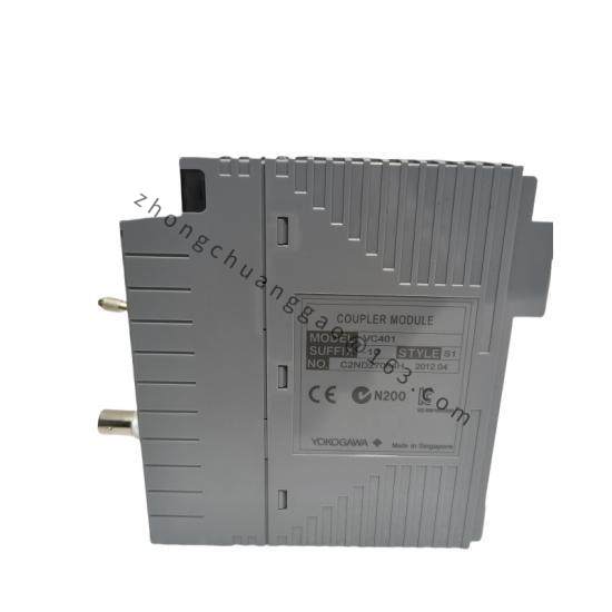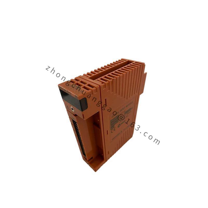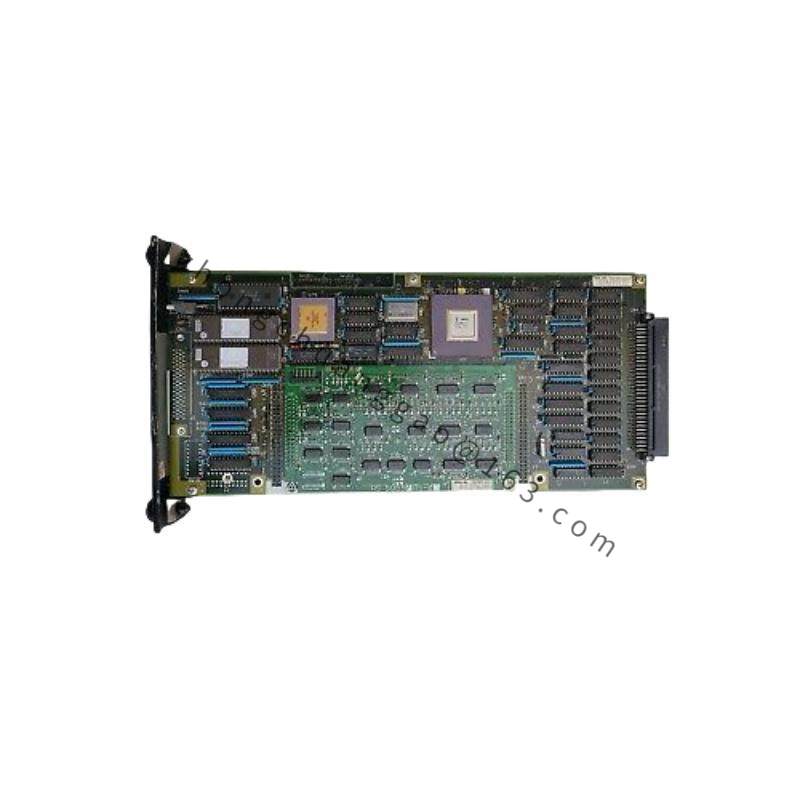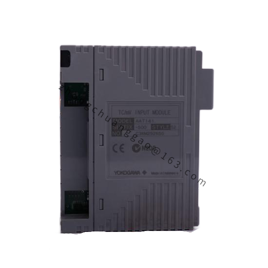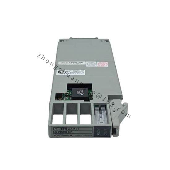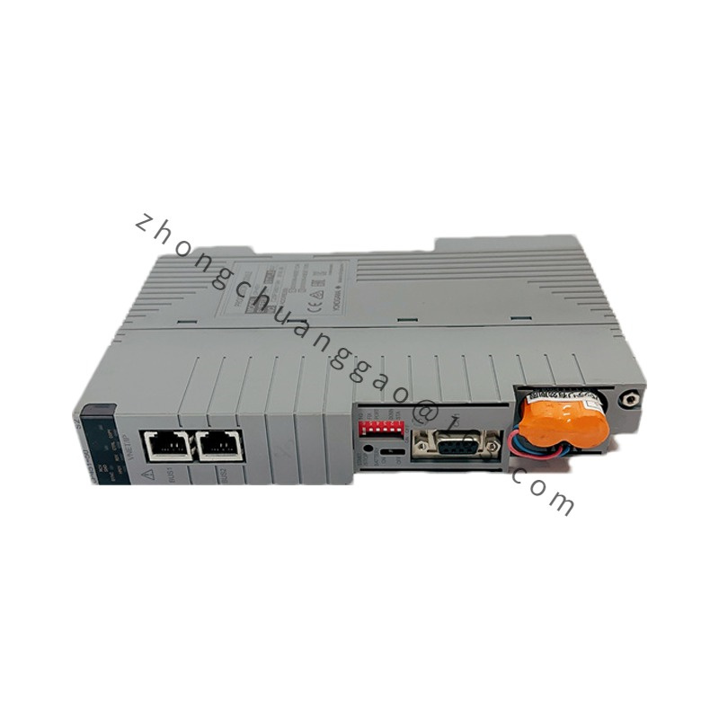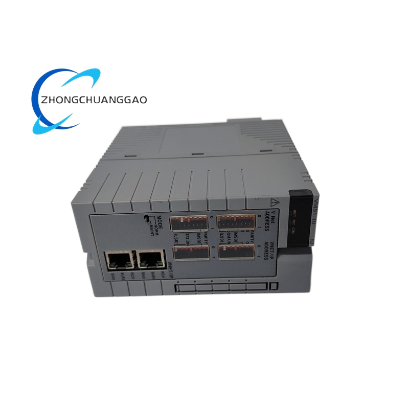
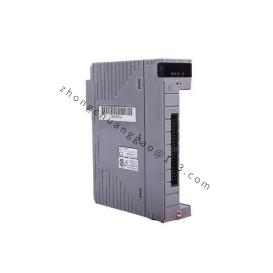
Yokogawa NFCP501-W1S1
Product Category: Foundation Fieldbus H1 Communication Interface Module
Overview:
The NFCP501-W1S1 is a single-channel Foundation Fieldbus H1 communication processor module for the Yokogawa F3 Series DCS. It serves as the bridge between the F3 control engine and Foundation Fieldbus H1 field devices (transmitters, actuators, valves), enabling full digital fieldbus integration within the CENTUM VP / CS 3000 distributed control system architecture.
Detailed content
Technical Specifications:
| Parameter | Value |
|---|---|
| Model Number | NFCP501-W1S1 |
| Communication Protocol | Foundation Fieldbus H1 (FF H1) — IEC 61158-2 |
| Number of Channels | 1 Channel (H1 segment) |
| Communication Speed | 31.25 kbps (fixed, H1 standard) |
| Maximum Devices per Segment | Up to 32 devices (including spur connections) |
| Maximum Segment Length | 1900m (with repeaters), 950m (without repeaters) at 31.25 kbps |
| Bus Power Supply | 24V DC ±10% (provided via F3 I/O carrier or external PSU) |
| Bus Current (max.) | ≤40mA per segment (typical load: 10–30mA) |
| Isolation | Galvanic isolation between F3 bus and H1 segment (1500V AC, 1 min) |
| Supported Function Blocks | AI (Analog Input), AO (Analog Output), PID, CS (Control Selector), AR (Arithmetic), CHAR (Characterizer), SPLIT (Splitter), INTG (Integrator), etc. |
| Supported Device Types | FF H1 Transmitters (pressure, temperature, flow, level, pH, etc.), FF H1 Valve Positioners, FF H1 Actuators |
| Diagnostics | Device status, communication error, short circuit, open circuit, ground fault, LAS (Link Active Scheduler) status |
| Redundancy | Non-redundant (single module); redundant operation requires 2 modules in separate carriers |
| Operating Temperature | 0°C to +55°C (+32°F to +131°F) |
| Storage Temperature | -20°C to +70°C (-4°F to +158°F) |
| Relative Humidity | 5% to 85% RH (non-condensing) |
| Power Consumption | ≤2W (typical, from F3 carrier backplane) |
| Approvals/Certifications | CE, UKCA, FM, CSA, ATEX (Zone 2), IECEx |
| Dimensions (W × H × D) | Approx. 25.4mm × 160mm × 120mm (standard F3 module format) |
| Weight | Approx. 300g (typical) |
Functional Features:
- Single H1 segment interface — connects up to 32 Foundation Fieldbus H1 devices on one segment
- Full FF H1 protocol stack — complies with IEC 61158 Type 1 and FF H1 specifications
- LAS (Link Active Scheduler) management — the module acts as LAS for the H1 segment, managing scheduled and unscheduled communication
- Function block execution — supports all standard FF function blocks including AI, AO, PID, CS, CALC, CHAR, SPLIT, INTG, ISEL, etc.
- Device description (DD) management — automatically loads device DDs from field devices for seamless integration
- Comprehensive diagnostics — real-time monitoring of communication status, device health, bus voltage, bus current, short circuit, ground fault, open circuit
- Online device replacement — hot-add/hot-remove FF devices without segment shutdown (subject to LAS scheduling)
- Configuration via CS 3000 — full engineering, parameterization, and diagnostics through Yokogawa System View / CENTUM VP Engineering Station
Structural Features:
- Front panel with LED indicators: Power (green), Communication (green), Fault (red), LAS Active (green)
- H1 fieldbus terminal block — shielded twisted pair connection with integrated bus terminator switch (120Ω terminator — user-selectable ON/OFF)
- F3 bus connector at rear for carrier backplane connection
- Galvanic isolation barrier between F3 internal bus and H1 field segment
- Conformal-coated PCB for enhanced reliability
- Bus terminator resistor (120Ω ±1%) — integrated, switchable via DIP switch or software
Working Principle:
The NFCP501-W1S1 connects to the F3 control engine via the high-speed F3 Bus. The internal FF H1 protocol processor encodes/decodes all communication frames between the DCS and field devices. The module operates as the LAS (Link Active Scheduler) on the H1 segment, managing scheduled communications (CD — Compel Data) and unscheduled communications (token-passing). Analog process data from FF H1 transmitters is received as digital function block outputs, converted to engineering units by the DCS, and displayed/controlled via the operator station. Control outputs from the DCS are sent as digital setpoints to FF H1 valve positioners or AO function blocks in field devices. The galvanic isolation barrier ensures that electrical faults on the fieldbus segment do not propagate to the DCS controller.
Advantages & Highlights:
- Full digital fieldbus integration — replaces dozens of analog 4–20mA wiring runs with a single twisted-pair segment
- Multidrop capability — up to 32 devices on one segment drastically reduces cabling costs
- Device-level diagnostics — pinpoints exact device faults (sensor, valve, wiring) from the control room
- Bidirectional communication — enables remote calibration, parameter changes, and device status monitoring
- Standard compliance — IEC 61158, FF H1, NAMUR NE 43 compliant
- Seamless CS 3000 integration — native function block library, no third-party configuration tools required
Applicable Industries:
- Oil & Gas — wellhead monitoring, pipeline metering, refinery process loops
- Chemical & Petrochemical — reactor control, distillation column instrumentation
- Power Generation — boiler feedwater control, turbine auxiliaries
- Water & Wastewater — flow measurement, chemical dosing
- Pharmaceutical — batch process instrumentation
- Mining & Metals — remote field instrumentation
Installation Requirements:
- Install in F3 I/O carrier (F3AIO/F3DIO) — any available slot (non-redundant module)
- Connect shielded twisted-pair cable (Type A, 120Ω characteristic impedance) to H1 terminal block
- Terminate both ends of the H1 segment with 120Ω resistor — enable terminator on this module (one end) and on the last device or remote terminator
- Connect shield drain wire to chassis ground (PE) at one end only (this module recommended)
- Ensure bus power (24V DC) is supplied — either from F3 carrier or external 24V PSU rated ≥100mA
- Configure LAS priority and scheduled communication interval in CS 3000 before commissioning
Usage Precautions:
- Do not exceed 32 devices per H1 segment (including spurs) — communication will degrade or fail
- Do not exceed 1900m total segment length at 31.25 kbps without repeaters
- Always enable bus terminator (120Ω) at exactly two points on the segment — missing or extra terminators cause communication errors
- Shield grounding must be at one end only — grounding at both ends creates ground loops and noise
- Do not mix FF H1 and HSE (Ethernet) devices on the same segment — they are incompatible physical layers
- Verify device DD files match the actual field devices — mismatched DDs cause function block errors
- For redundant operation, install a second NFCP501-W1S1 in a separate F3 carrier with independent H1 segment connection