

Digital guide

You are here:

YOKOGAWA FX1004-4-3-H

Product Introduction:
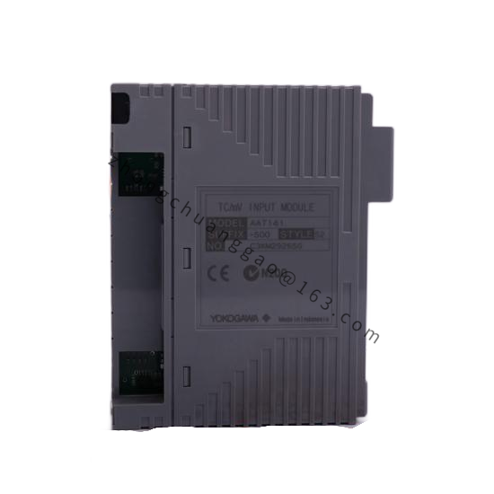
The FX1004-4-3-H is a 4-channel input, 3-channel output signal converter from Yokogawa’s FX1000 series. It accepts universal analog inputs (thermocouple, RTD, voltage, current) and converts them to isolated analog outputs. The “H” designation indicates horizontal mounting orientation. It is used for signal isolation, conversion, and distribution in process control systems where galvanic isolation between input and output is required.

Detailed content

Technical Specifications:

  • Model: FX1004-4-3-H
  • Series: FX1000
  • Number of Input Channels: 4 universal inputs (4)
  • Number of Output Channels: 3 isolated outputs (3)
  • Mounting OrientationHorizontal (H)
  • Input Types: Type K, J, T, E, R, S, B thermocouples; Pt100, Pt1000, Cu50, Cu100 RTDs; 0–100 mV, 0–5 V, 1–5 V, 0–20 mA, 4–20 mA
  • Output Types: 4–20 mA DC (3 channels, galvanically isolated)
  • Isolation500 V AC between input and output, 250 V AC between outputs
  • Power Supply: 24 V DC (operating range: 18–36 V DC) or 100–240 V AC
  • Accuracy: ±0.2% of span (input), ±0.1% of span (output)
  • Response Time: ≤ 0.5 seconds
  • Operating Temperature: -10 °C to +55 °C
  • Protection Class: IP20 (indoor use)
  • Dimensions: 120 × 60 × 90 mm (W × H × D) for horizontal mounting
  • Weight: Approximately 0.4 kg

Functional Features:

  • Input-to-output signal conversion (e.g., TC input → 4–20 mA output)
  • Input-to-output signal retransmission with galvanic isolation
  • Linearization for thermocouple and RTD inputs
  • Cold junction compensation (CJC) for thermocouple inputs (built-in)
  • Programmable input range and output range via DIP switches or PC software
  • LED status indicators for each channel (power, input, output, fault)

Performance Parameters:

  • Input Impedance: 10 MΩ (voltage input), 100 Ω (current input)
  • Output Load: 0–600 Ω (4–20 mA output)
  • Isolation Voltage: 500 V AC (1 minute, input to output)
  • Dielectric Strength: 1,500 V AC (1 minute, input to chassis)
  • Common Mode Rejection Ratio (CMRR): ≥ 120 dB
  • Power Consumption: ≤ 5 W (24 V DC supply)

Material Composition:

  • Housing: Flame-retardant polycarbonate (UL94 V-0)
  • Terminal Block: Phoenix-type, nickel-plated brass screws
  • PCB: FR-4 glass epoxy, conformally coated
  • Internal Shielding: Copper foil EMI shielding between input and output sections

Structural Features:

  • DIN rail mounting (35 mm top-hat rail) — horizontal orientation
  • Screw-terminal wiring from the front (removable cover)
  • 4 input terminal blocks and 3 output terminal blocks, clearly labeled
  • LED indicators on the front face for each channel
  • Compact form factor suitable for control cabinet installation

Working Principle:
The FX1004 receives process signals on its 4 universal input channels. Each input is conditioned by dedicated signal conditioning circuitry (amplification, filtering, cold junction compensation for TC, linearization for RTD). The conditioned signal is then converted by a high-resolution A/D converter. The digital value is processed by the internal microprocessor and converted back to an analog signal by a precision D/A converter. The analog output is galvanically isolated from the input via an isolation transformer or opto-isolator and delivered as a 4–20 mA signal on one of the 3 output channels. Each output channel is independently isolated from the others.

Advantages & Highlights:

  • Galvanic isolation (500 V AC) eliminates ground loops and noise interference
  • 4 inputs to 3 outputs provides flexible signal routing and distribution
  • Built-in cold junction compensation eliminates the need for external CJC modules
  • DIP switch configurable — no software required for basic setup
  • Horizontal DIN rail mounting (H) saves vertical space in crowded control cabinets

Applicable Industries:

  • Process Control Systems (DCS/PLC I/O isolation)
  • Building Automation (HVAC signal distribution)
  • Industrial Automation (signal conditioning for analog I/O)
  • Power Generation (turbine and generator monitoring)
  • Water and Wastewater (pump and valve control)
  • Food and Beverage (sanitary signal isolation)

Installation Requirements:

  • Mount on 35 mm DIN rail in a horizontal orientation
  • Provide 24 V DC power supply (18–36 V DC) or 100–240 V AC
  • Use shielded twisted-pair cables for TC/RTD inputs; ground shield at the FX1004 end
  • Maintain minimum 20 mm separation between the FX1004 and high-power devices (VFDs, contactors)
  • Configure DIP switches according to the desired input/output range before connecting signals

Usage Precautions:

  • Do not exceed the maximum isolation voltage of 500 V AC between input and output — this will destroy the isolation barrier
  • Verify input signal range matches the DIP switch setting before applying signals
  • Do not short-circuit the 4–20 mA output terminals
  • Ensure the power supply voltage is within the 18–36 V DC range (for 24 V DC operation)
  • Do not install in locations with ambient temperature exceeding +55 °C
  • Tighten all terminal screws to 0.5 N·m torque to ensure reliable contact
  • Perform zero and span calibration annually using a precision calibrator

You may also like