

YOKOGAWA F3YP04-0N
Product Series: F3/F4 Series PLC Special Function Modules
Product Introduction:
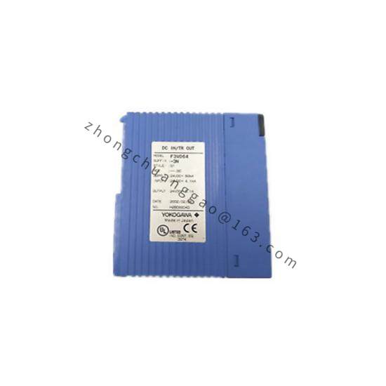
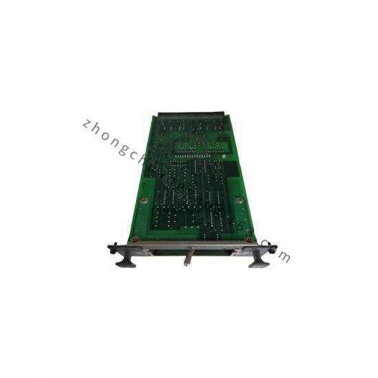
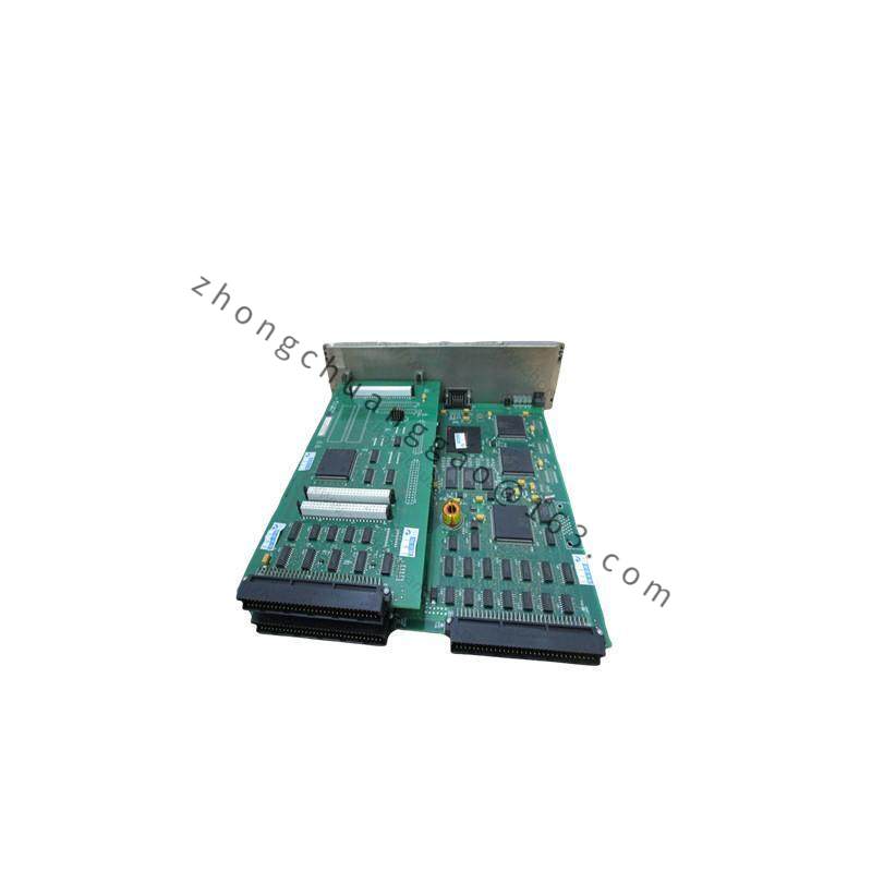
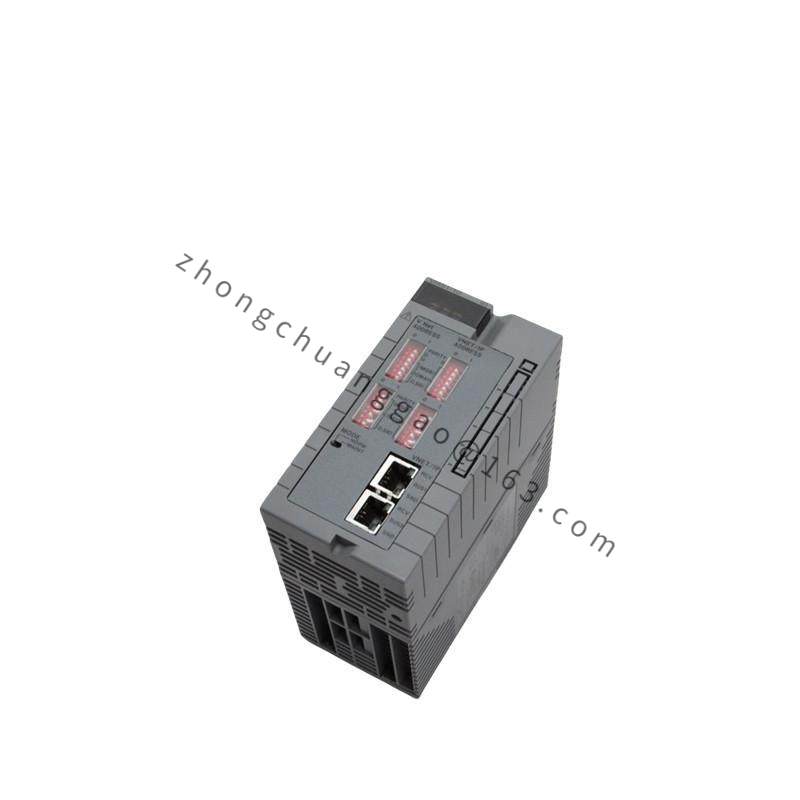
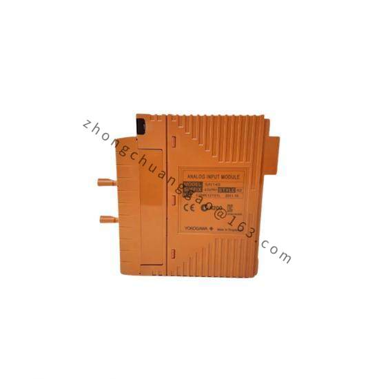
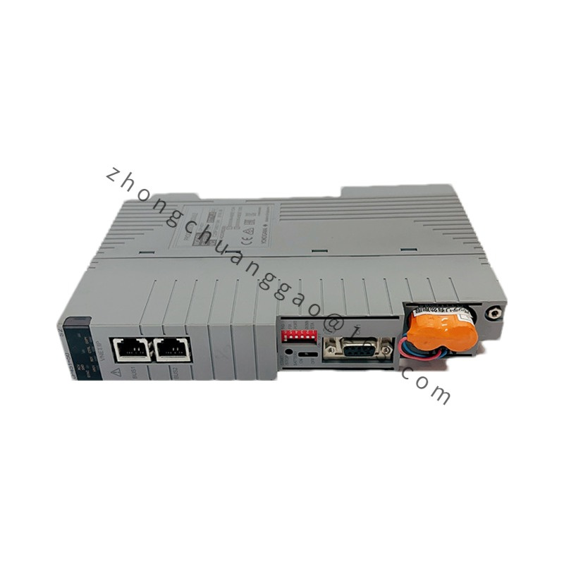
The F3YP04-0N is a 4-channel pulse (transistor) output module for the Yokogawa F3/F4 series PLC. It generates high-speed pulse trains for controlling stepping motors, servo drives, and other pulse-input devices. It is commonly used in positioning, counting, and speed control applications.
Detailed content
Technical Specifications:
- Module Type: Pulse Output (Transistor — NPN open collector)
- Number of Channels: 4 independent channels
- Output Type: NPN transistor (open collector)
- Maximum Pulse Frequency: 100 kHz per channel
- Output Voltage: 5–24 VDC (external supply required)
- Maximum Output Current: 50 mA per channel (sink current)
- Pulse Mode: Pulse + Direction, CW/CCW, Up/Down
- Resolution: 1 pulse per command (no sub-division)
- Isolation Voltage: 500 VDC (channel-to-channel, channel-to-bus)
- Power Supply: 5 VDC from PLC backplane bus
- Current Consumption: 150 mA (typ.) from backplane
- Operating Temperature: 0°C to +55°C (+32°F to +131°F)
- Dimensions (W × H × D): 25 mm × 90 mm × 85 mm
- Weight: Approximately 0.08 kg
Functional Features:
- 4 independent pulse outputs — can control 4 axes simultaneously
- Pulse + Direction mode — standard for stepper/servo drives
- CW/CCW and Up/Down modes — flexible for different drive types
- On-the-fly frequency change — pulse frequency can be updated while output is active
- LED status indicator per channel (output active, error)
- Buffer memory — stores up to 8192 pulses per channel for burst output
Structural Features:
- Standard F3/F4 module form factor
- DIN rail mountable in PLC rack
- Screw-terminal block for pulse output signals (Pulse+, Pulse-, Direction+, Direction-) per channel
- Opto-isolated outputs for noise immunity
Working Principle:
The PLC CPU writes target pulse count and frequency to the module’s internal registers via the backplane bus. The module’s internal pulse generator produces a square wave at the specified frequency on the Pulse+ output. The Direction output sets the rotation direction (high = CW/Up, low = CCW/Down). The NPN open-collector outputs sink current from an external 5–24 VDC supply connected to the load (stepper driver, servo amplifier, counter). The module counts down the pulse count and stops automatically when the target is reached, or runs continuously if set to free-run mode.
Advantages & Highlights:
- 100 kHz max frequency — supports high-speed servo and stepper control
- 4 independent channels — multi-axis control from a single module
- 8192-pulse buffer — enables complex motion profiles without CPU intervention
- NPN open-collector outputs — compatible with most stepper/servo drive inputs
- Opto-isolation — protects the PLC from back-EMF and electrical noise from motors
Applicable Industries:
- CNC machine tools (axis control)
- Packaging machinery (filling, sealing, labeling)
- Conveyor systems (speed and position control)
- Textile machinery
- Robotics (joint control)
Installation Requirements:
- Insert into F3/F4 PLC rack at the designated slot
- Connect external 5–24 VDC power supply to the load side of each channel (Pulse+ and Direction+ lines)
- Use shielded cable for pulse output lines — keep away from power cables (≥ 100 mm separation)
- Set the pulse output mode (Pulse+Direction / CW+CCW / Up+Down) in the PLC program before operation
Usage Precautions:
- Never connect the pulse output directly to AC mains or voltages above 24 VDC — will destroy the transistor outputs
- The external power supply for the load must be able to source at least 50 mA per active channel
- Do not exceed 100 kHz per channel — higher frequencies cause missed pulses
- Use a snubber circuit (RC) across inductive loads (relay coils, solenoids) to suppress back-EMF
- Verify pulse count and direction in simulation mode before connecting to actual machinery