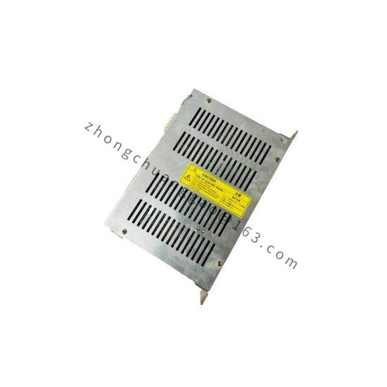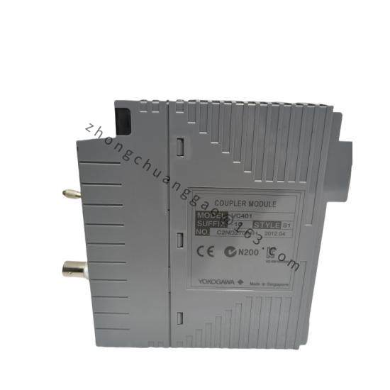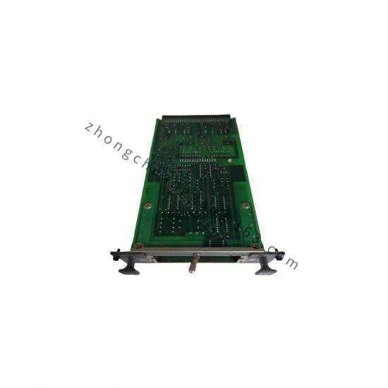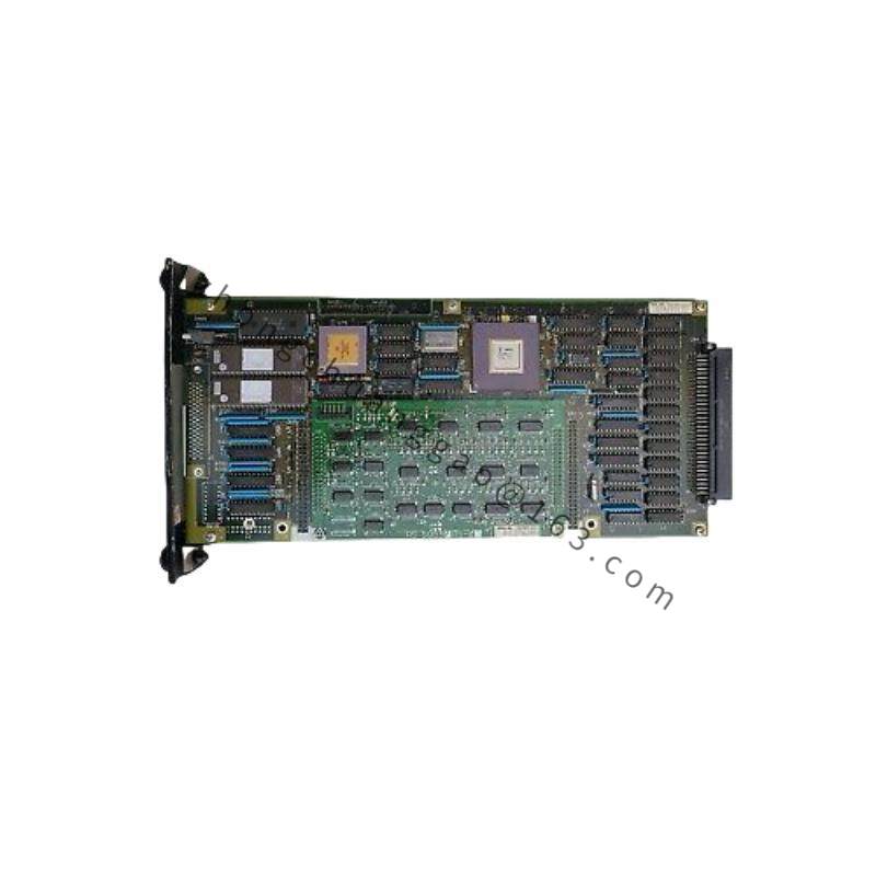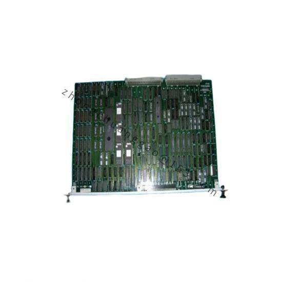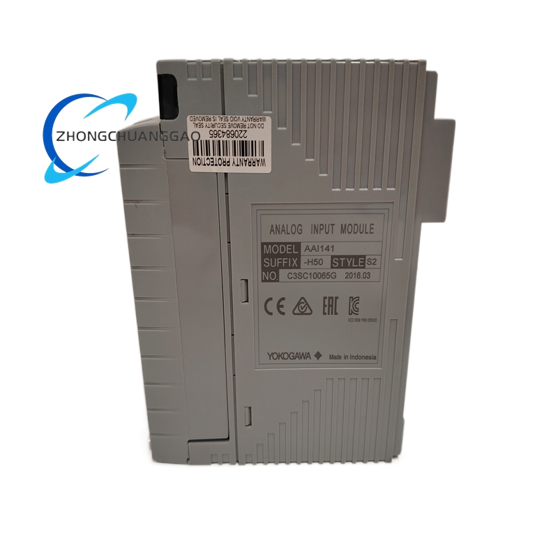

Yokogawa F3SP28-3S
Product Overview:
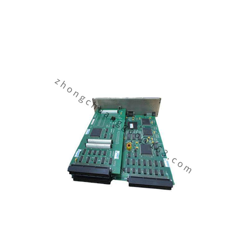
The F3SP28-3S is a Safety Integrity Level 3 (SIL3) certified safety controller from Yokogawa’s F3SP series. It features a triple modular redundant (TMR) architecture with 3 independent CPUs executing the same program in parallel. A 2-out-of-3 (2oo3) voting mechanism ensures fault tolerance. The unit is designed for Emergency Shutdown (ESD) and Safety Instrumented Functions (SIF) in hazardous process environments.
Detailed content
Technical Specifications:
| Parameter | Value |
|---|---|
| Safety Integrity Level | SIL 3 (IEC 61508), SIL 3 (IEC 61511) |
| Architecture | Triple Modular Redundancy (TMR) — 3 CPUs with 2oo3 voting |
| Number of I/O Points | 28 points (configurable: DI, DO, AI, AO via F3 I/O modules) |
| CPU Type | 32-bit RISC processor, operating frequency: 80 MHz |
| Program Memory | 2 MB (Flash) for application program + 1 MB for data |
| Data Memory | 512 KB RAM (non-volatile backup) |
| Cycle Time | Typical: 10 ms (basic instruction), 50 ms (with 28 I/O points) |
| Input Modules Supported | F3AI (Analog Input), F3DI (Digital Input), F3TC (Thermocouple Input), F3RTD (RTD Input) |
| Output Modules Supported | F3AO (Analog Output), F3DO (Digital Output), F3SO (Safe Output) |
| Communication | F3 Fieldbus (Yokogawa proprietary safety bus), Ethernet (Modbus TCP for non-safety) |
| Redundancy | CPU: TMR (2oo3), Power Supply: Dual redundant, Communication: Dual redundant |
| Power Supply | 24 V DC (dual redundant inputs, hot-swappable) |
| Power Consumption | Approximately 8 W (CPU module only, typical) |
| Operating Temperature | 0°C to +60°C (wide temperature range version available: -20°C to +70°C) |
| Humidity | 5% to 95% RH (non-condensing) |
| Enclosure | Metal enclosure, DIN rail or panel mount |
| Dimensions (W × H × D) | Approximately 150 mm × 120 mm × 90 mm (CPU module) |
| Weight | Approximately 1.2 kg (CPU module) |
| Certifications | IEC 61508 SIL3, IEC 61511 SIL3, ATEX Zone 2, IECEx, CSA Class I Div 2, FM Class I Div 2 |
| Diagnostic Coverage | Greater than 99% (for dangerous undetected failures) |
| Proof Test Interval | Up to 10 years (depending on application and SIF) |
| MTTF (Mean Time To Failure) | Greater than 100 years (for dangerous failures, per IEC 61508 calculations) |
| PFDavg (Average Probability of Failure on Demand) | 1.0 × 10⁻³ to 1.0 × 10⁻² (depending on configuration and proof test interval) |
Functional Features:
- Triple Modular Redundancy (TMR): Three CPUs execute identical programs; 2oo3 voter compares outputs and masks single CPU failures
- Online diagnostics: Continuous self-diagnosis of CPU, memory, I/O modules, and communication
- Safe Output Modules (F3SO): Certified safe relay outputs with forced-guided contacts for ESD valve actuation
- Fail-safe design: All outputs default to safe state (de-energized for ESD, energized for fire & gas) on power loss or fault
- Programming: IEC 61131-3 compliant languages: Ladder Diagram (LD), Function Block Diagram (FBD), Structured Text (ST), Sequential Function Chart (SFC)
- Non-volatile memory: Program and data retained without battery backup
- Hot-swappable: CPU, power supply, and I/O modules can be replaced without system shutdown (with redundancy)
- Event logging: Comprehensive diagnostic event log with timestamps
Working Principle:
The F3SP28-3S uses 3 independent CPUs running the same user program simultaneously. Each CPU reads inputs, executes the logic, and produces outputs. A hardware voter compares the 3 outputs and selects the majority result (2oo3). If one CPU fails or produces an incorrect result, the other two outvote it, and the system continues operating without interruption. The voting occurs at the output stage, ensuring that a single point of failure does not cause a spurious trip or failure to trip. All safety outputs use forced-guided relay contacts that are mechanically linked to detect contact weld failures.
Advantages and Highlights:
- SIL3 certified (IEC 61508/61511) — highest safety integrity level for process safety
- TMR architecture provides continuous operation with zero-downtime fault masking
- 99%+ diagnostic coverage enables extended proof test intervals (up to 10 years)
- IEC 61131-3 programming uses familiar PLC programming languages
- Yokogawa F3 ecosystem — seamless integration with F3 I/O, F3 fieldbus, and CENTUM VP DCS
- Wide temperature range option (-20°C to +70°C) for extreme environments
- Dual redundant power supply with hot-swap capability
Applicable Industries:
- Oil and Gas (onshore/offshore platforms, refineries, LNG)
- Chemical and Petrochemical
- Pharmaceutical
- Nuclear Power
- Hydrogen Production
- Mining and Minerals
Installation Requirements:
- Mount on DIN 35mm rail (EN 50022) or panel-mount using supplied brackets
- Install in a clean, dry environment with ambient temperature 0°C to +60°C (or -20°C to +70°C for wide-range version)
- Connect dual 24V DC power supplies with proper redundancy wiring (A/B feeds)
- Use F3 fieldbus cables (shielded twisted pair) for I/O module connections
- Install forced-guided relay interfaces between F3SO outputs and final elements (solenoid valves)
- Ensure proper grounding of chassis and shield drains
- Maintain minimum 50mm spacing between modules for heat dissipation
Usage Precautions:
- Never modify the safety program without a certified functional safety engineer performing a full SIL re-assessment
- Perform proof tests at intervals not exceeding the calculated PFDavg requirement (typically every 1-10 years depending on SIF)
- Do not connect non-safety signals to safety I/O modules
- Verify all forced-guided relay contacts are functioning correctly during commissioning
- Do not bypass or defeat any safety diagnostic function
- Maintain complete documentation of the safety lifecycle (hazard analysis, SIF design, validation, operation) per IEC 61511
- Use only Yokogawa-approved I/O modules with the F3SP CPU