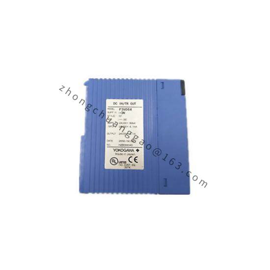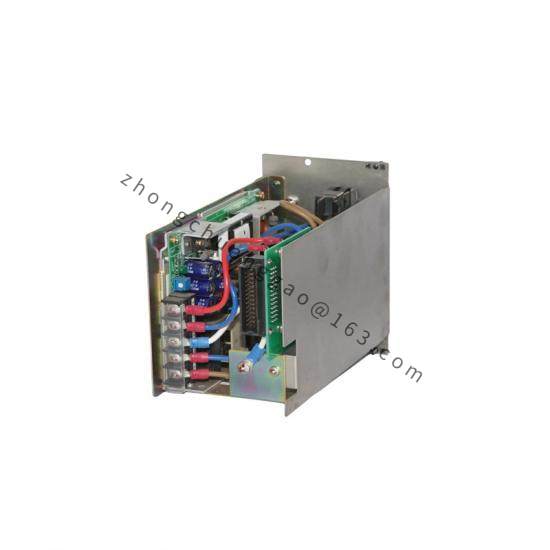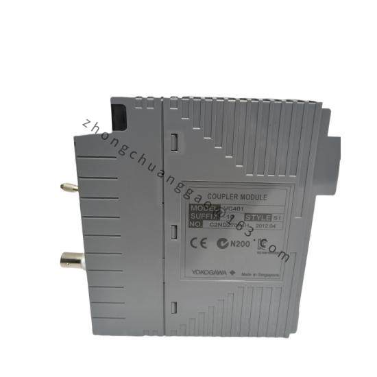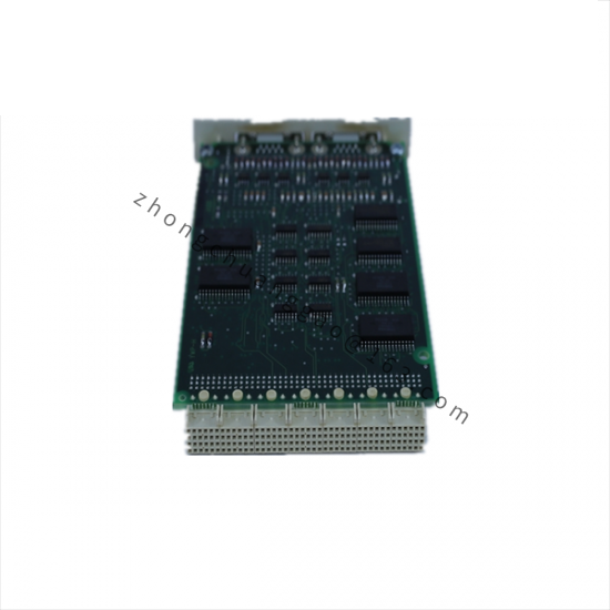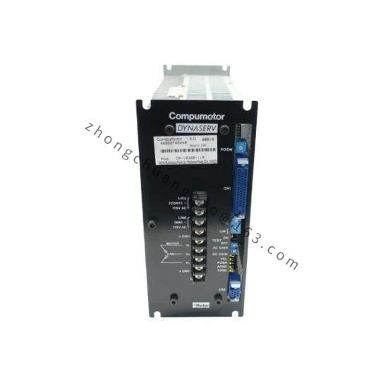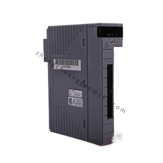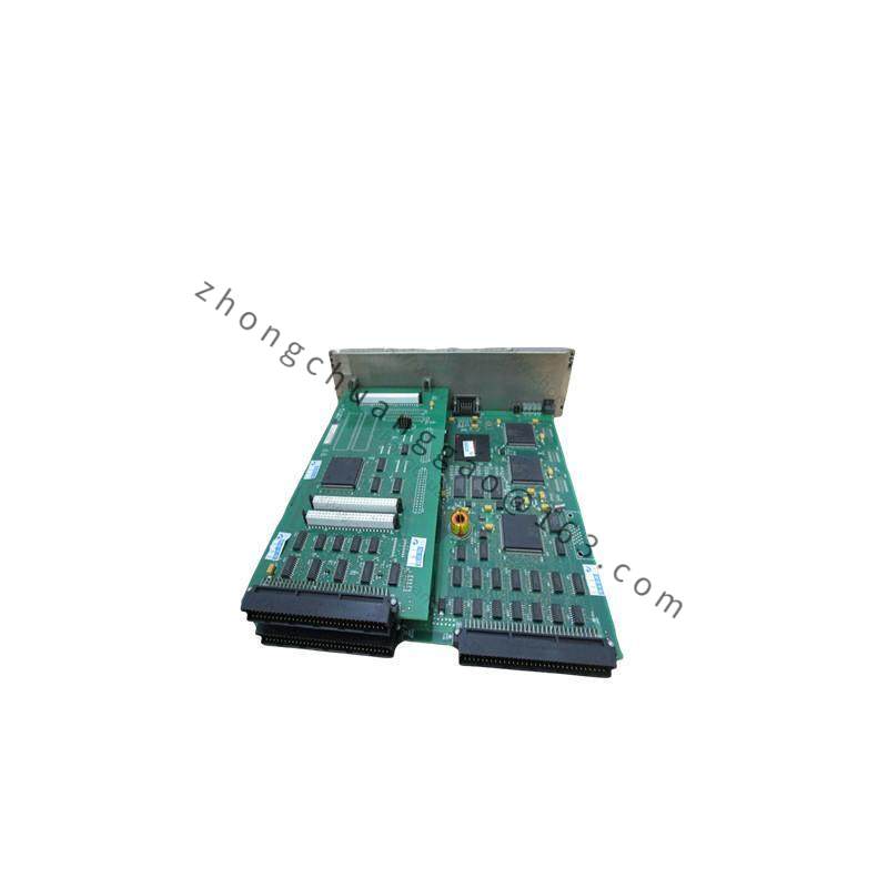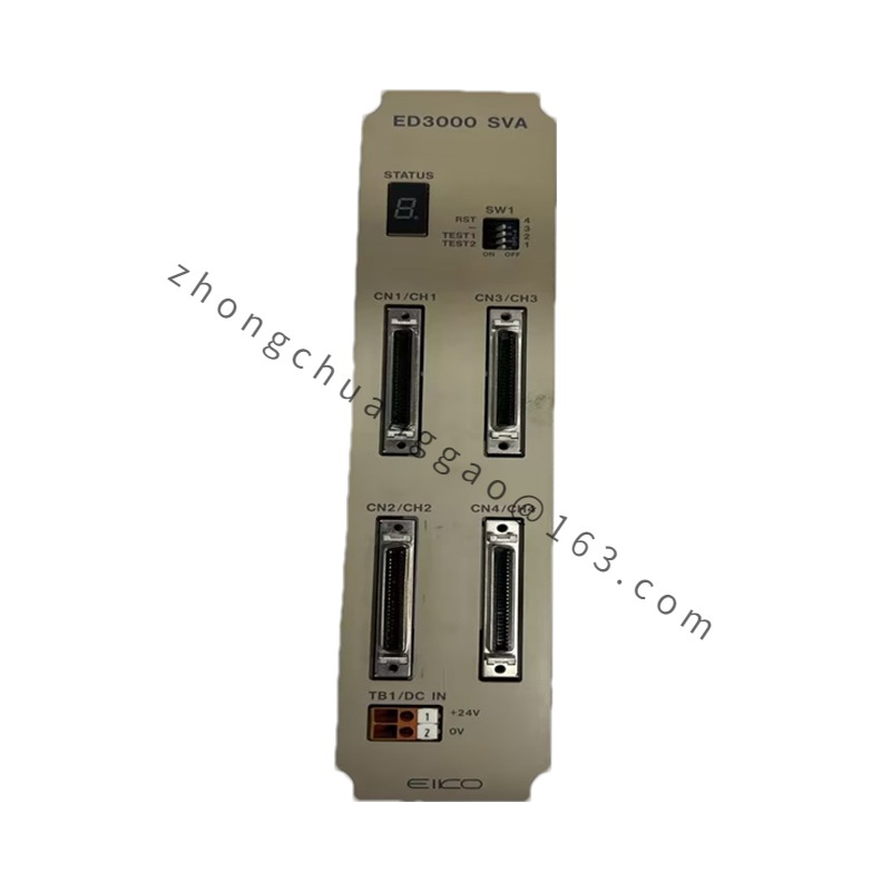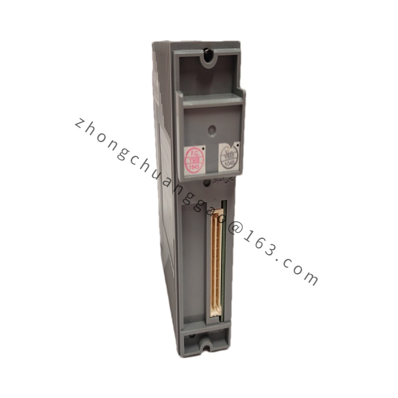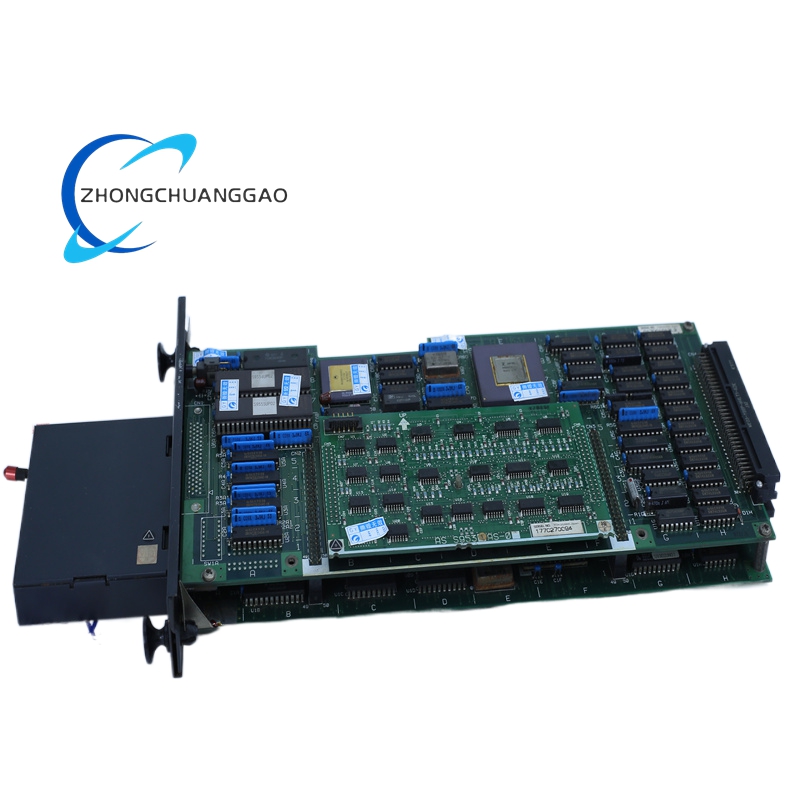
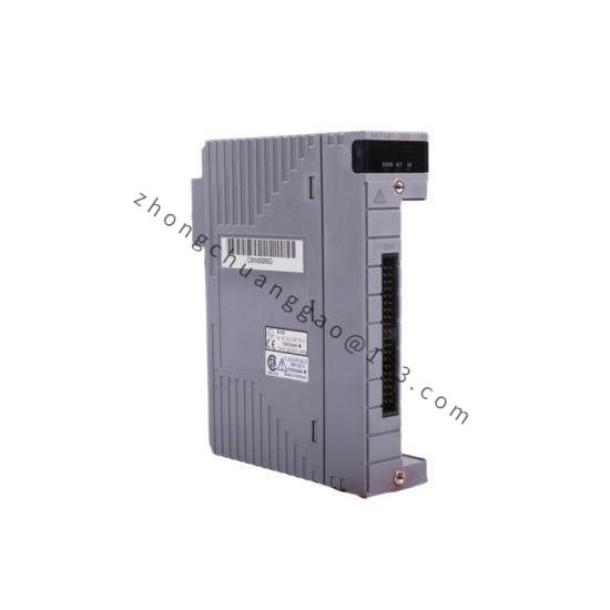

YOKOGAWA F3RP56-2H/L1/C
Product Introduction:
The F3RP56-2H/L1/C is a 2-wire loop-powered signal isolator and splitter from Yokogawa’s F3RP product family. It provides galvanic isolation between input and output signals while being powered entirely from the 4–20 mA loop current, eliminating the need for a separate power supply. The device converts and distributes process signals to multiple outputs with full electrical isolation.
Detailed content
Technical Specifications:
| Parameter | Value |
|---|---|
| Input Signal | 4–20 mA DC / 1–5 V DC / 0–10 V DC (selectable) |
| Output Signal | 4–20 mA DC (2 channels) |
| Isolation Voltage | 1500 V AC (1 minute) |
| Supply Voltage | 12–42 V DC (loop-powered) |
| Accuracy | ±0.2% of span |
| Response Time | ≤ 200 ms (typ.) |
| Operating Temperature | -20°C to +70°C |
| Protection Rating | IP20 (DIN rail mount) |
| Configuration Code | 56 = 2-input / 2-output isolator |
| Option L1 | Linear output characteristic |
| Option C | Communication-ready / HART compatible interface |
| Mounting | DIN rail (EN 60715), 35 mm |
| Weight | Approx. 150 g |
Functional Features:
- Galvanic isolation between all input and output channels
- 2-input / 2-output signal splitting with independent isolation per channel
- Loop-powered operation — no external power supply required
- HART communication capability (Option C)
- Fail-safe output configurable to high, low, or hold last value
- Zero and span adjustment via front panel or HART communicator
Material Composition:
- Housing: Flame-retardant polycarbonate (UL94 V-0 rated)
- Terminals: Phosphor bronze with tin plating
- PCB: FR-4 glass epoxy, conformal coated
Structural Features:
- Slim DIN rail module design — 22.5 mm width
- Screw-clamp terminal connections for secure wiring
- LED status indicator for operation/alarm status
- IP20 front face protection
Working Principle:
The device draws operating power from the 4–20 mA loop current. The input signal is conditioned, isolated via high-frequency transformer isolation (1500 V AC), and converted to a proportional output current on each isolated output channel. The isolation barrier prevents ground loops and suppresses common-mode noise.
Advantages & Highlights:
- Eliminates ground loop problems in multi-instrument installations
- Reduces wiring costs by splitting one signal to two destinations
- Intrinsically safe when used with appropriate barriers in hazardous areas
- HART protocol support enables remote configuration and diagnostics
Applicable Industries:
- Oil & Gas
- Chemical / Petrochemical
- Power Generation
- Water & Wastewater Treatment
- Pharmaceutical Manufacturing
- Food & Beverage Processing
Installation Requirements:
- Mount on DIN rail EN 60715 (35 mm)
- Ensure loop supply voltage ≥ 12 V DC at maximum load
- Maintain minimum 25 mm clearance above and below for heat dissipation
- Use shielded twisted-pair cable for noise-prone environments
Usage Precautions:
- Do not exceed 42 V DC loop supply voltage
- Verify input signal range matches configuration before energizing
- Ensure proper grounding of signal shields at one end only
- Do not open housing in hazardous areas — servicing must comply with ATEX/IECEx requirements where applicable