
Product Introduction:
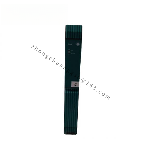
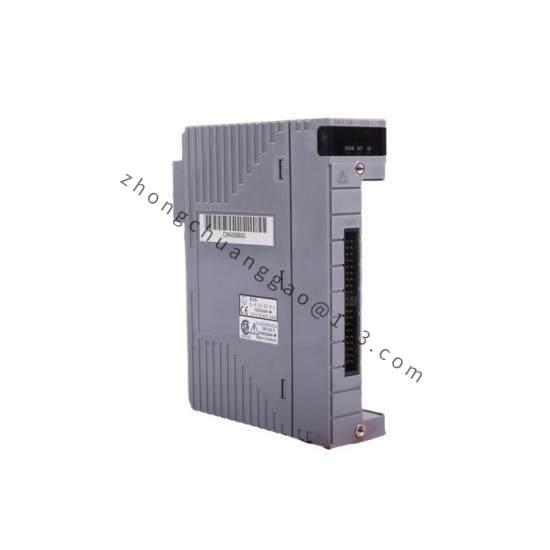
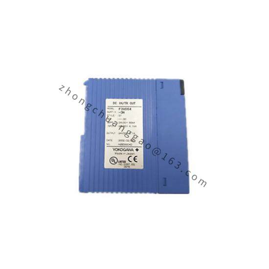
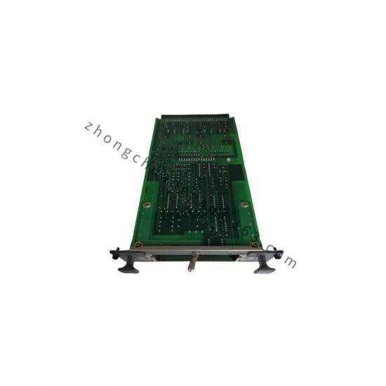
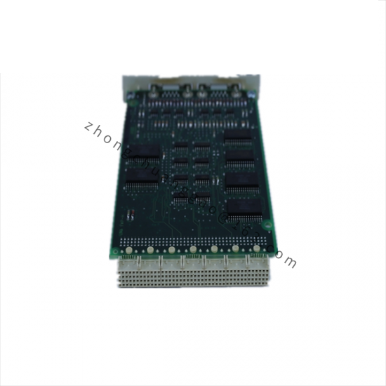
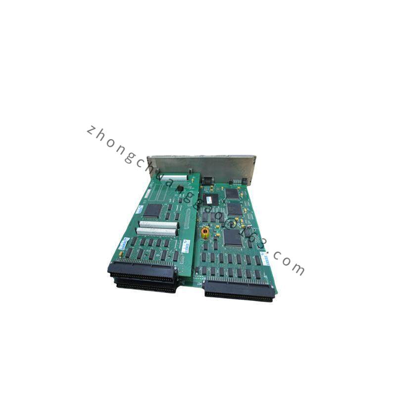
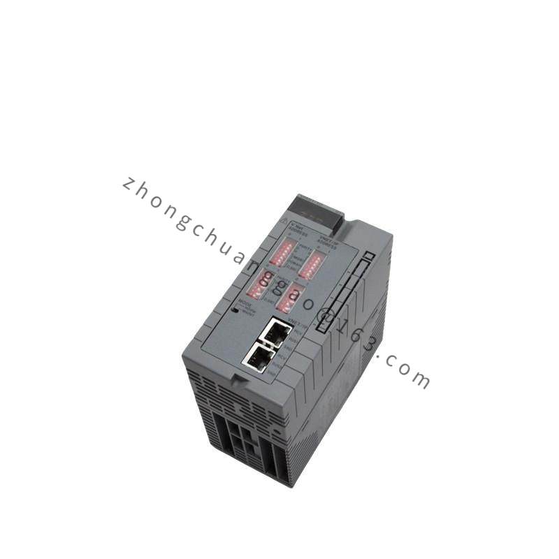
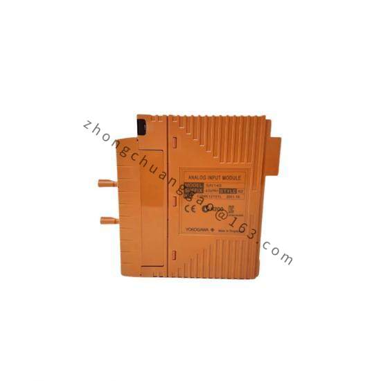
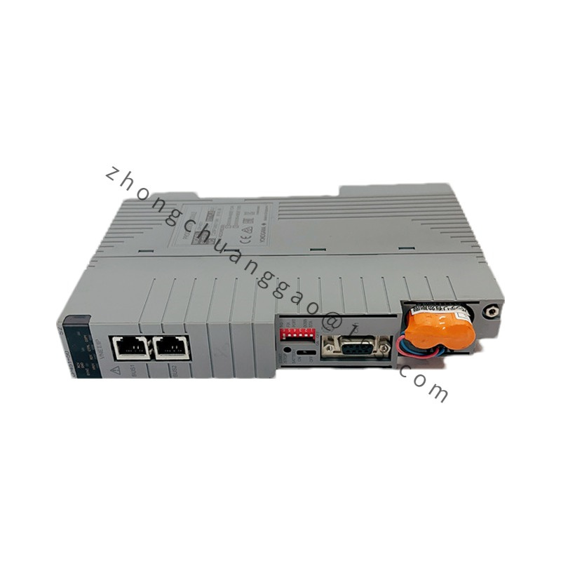
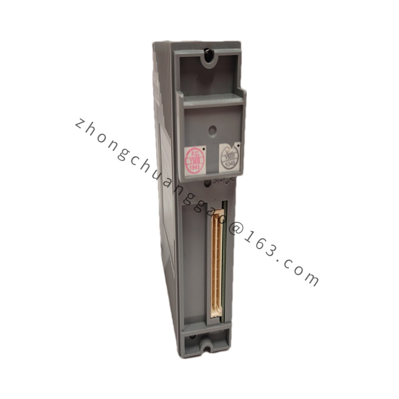
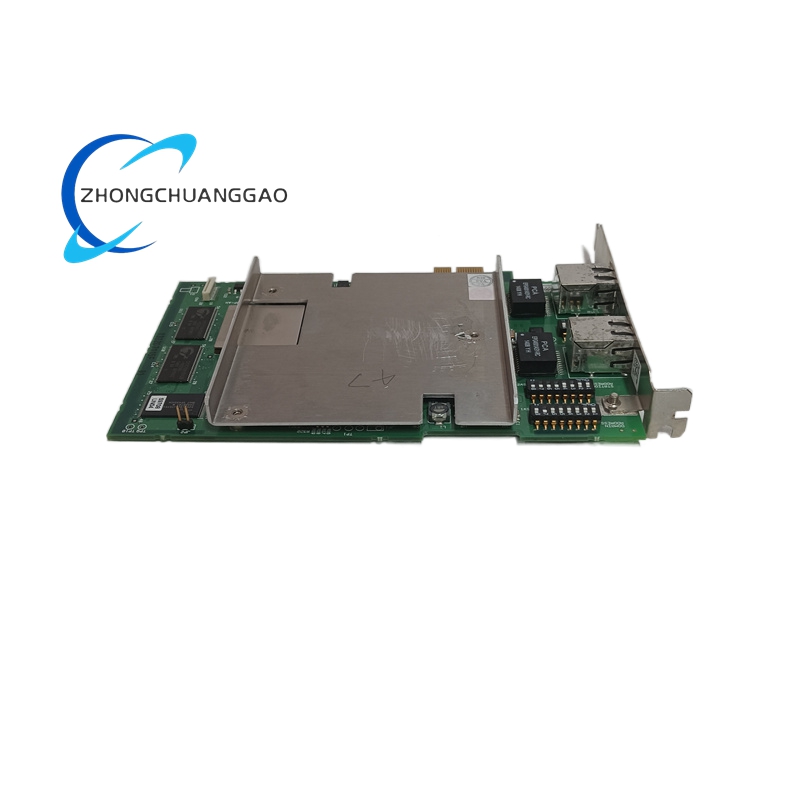
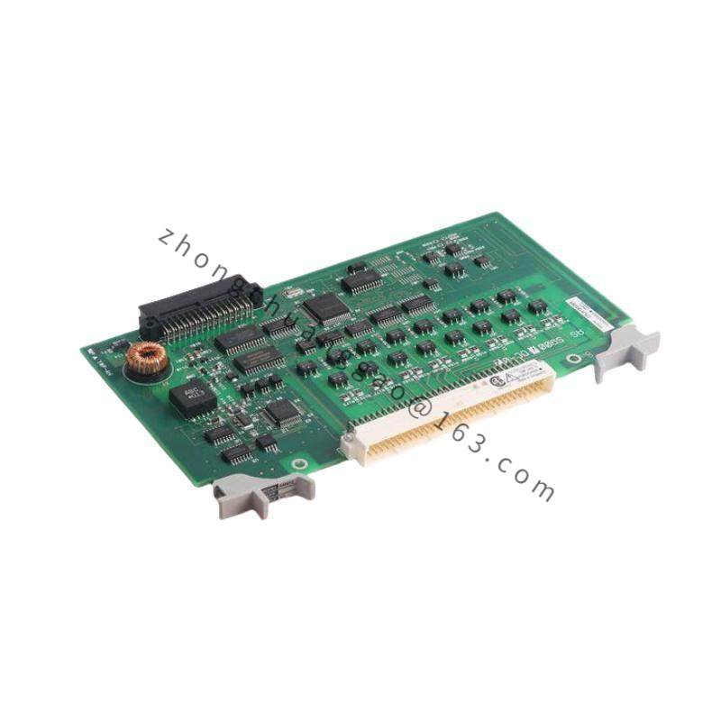
The F3NC61-0N is a compact programmable logic controller CPU module from Yokogawa Electric Corporation’s F3NC Series, designed for small-to-medium scale automation applications. It serves as the central processing unit of the F3NC PLC system, executing user programs, managing I/O data, and handling communication tasks. The 0N suffix indicates this is a base model without built-in network/Ethernet functionality, intended for standalone control applications where advanced networking is not required.
Technical Specifications:
| Parameter | Specification |
|---|---|
| I/O Points | 61 points (32 digital inputs + 29 digital outputs) |
| Program Capacity | Approximately 8,000 steps |
| Program Memory | RAM + EEPROM backup |
| Communication Port | RS-422 (built-in), supports Modbus RTU protocol |
| Network Function | None (0N = base model, no Ethernet/IP) |
| Power Supply Voltage | 24V DC (±10%) |
| Power Consumption | Approximately 2.5W |
| CPU Scan Speed | Basic instruction: ~0.55μs/step |
| Input Specifications | 24V DC, optocoupler isolated, ~5mA/point, response time ~10ms (filter adjustable) |
| Output Specifications | Relay output (contactless), 2A/point, 240V AC or 30V DC, response time ~10ms |
| Operating Temperature | 0°C to +55°C |
| Storage Temperature | -20°C to +70°C |
| Humidity Range | 5% to 95% RH (non-condensing) |
| Installation Method | DIN rail mounting (35mm standard rail) |
| Protection Rating | IP20 (front panel) |
Material Composition:
Structural Features:
Working Principle:
The F3NC61-0N operates on a cyclic scan mechanism consisting of three phases: input sampling → program execution → output refresh. The CPU reads field signal states from input modules, executes user-written ladder logic/instruction list programs, and outputs computation results to output modules to drive external actuators. The complete scan cycle ranges from several milliseconds to tens of milliseconds, ensuring real-time control response.
Functional Features:
Advantages & Highlights:
Applicable Industries:
Installation Requirements:
Usage Precautions: