
Product Overview:
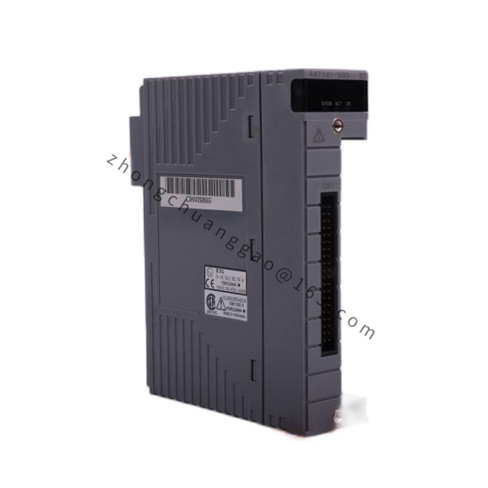
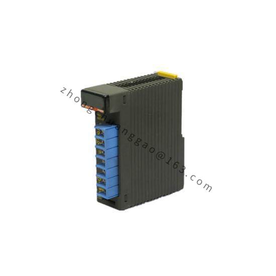
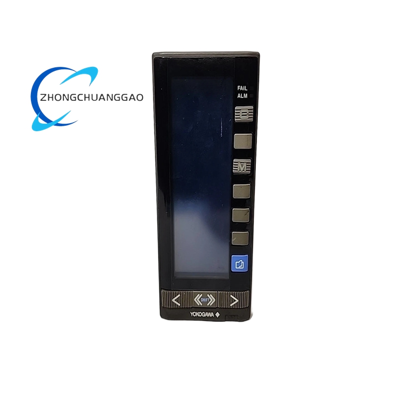
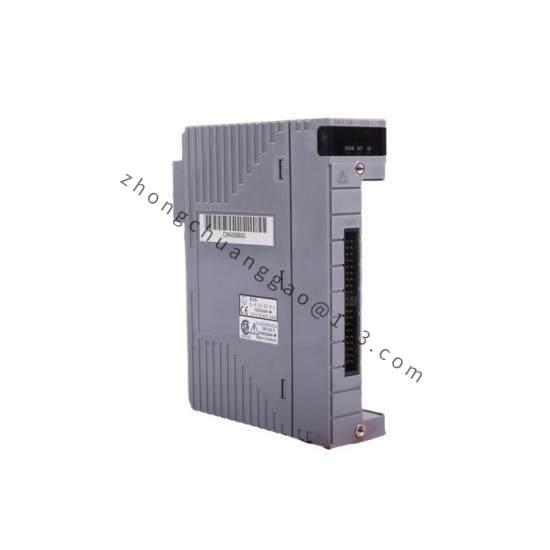
The F3CX04-ON is a 4-channel analog input module for Yokogawa’s F3 (FAST/TOOLS) Series Programmable Logic Controller (PLC). The 04 indicates 4 input channels. The -ON suffix denotes no local LCD display (non-display type). This module accepts 4–20 mA DC and 1–5 V DC input signals and converts them to 12-bit digital values for the PLC processor.
Technical Specifications:
| Parameter | Value |
|---|---|
| Number of Channels | 4 channels (single-ended) |
| Input Signal Type | 4–20 mA DC / 1–5 V DC (selectable per channel) |
| Resolution | 12-bit (4096 steps) |
| Conversion Time | 1 ms per channel (4 channels scanned in 4 ms total) |
| Input Impedance (Current) | 250 Ω (for 4–20 mA input) |
| Input Impedance (Voltage) | 1 MΩ minimum (for 1–5 V input) |
| Isolation | Non-isolated (field-side reference to CPU-side common) |
| Accuracy | ±0.1% of full scale (at 25°C) |
| Temperature Drift | ±0.02% of full scale per °C |
| Power Consumption | 0.9 W (from CPU bus) |
| Operating Temperature | 0°C to +55°C |
| Storage Temperature | -20°C to +70°C |
| Dimensions | 25 mm (W) × 90 mm (H) × 85 mm (D) |
| Weight | Approximately 80 g |
| Mounting | DIN rail (35 mm) or direct CPU backplane mounting |
Functional Features:
Working Principle:
The module uses a precision resistor network and 12-bit successive approximation ADC to convert analog input signals to digital values. For 4–20 mA input, the signal passes through a 250 Ω shunt resistor, producing a 1–5 V drop that is digitized. For 1–5 V input, the signal is directly fed to the ADC. The converted digital value is transferred to the F3 CPU via the backplane bus during each scan cycle. The CPU applies scaling and engineering unit conversion in the user program.
Advantages:
Applicable Industries:
Installation Requirements:
Usage Precautions: