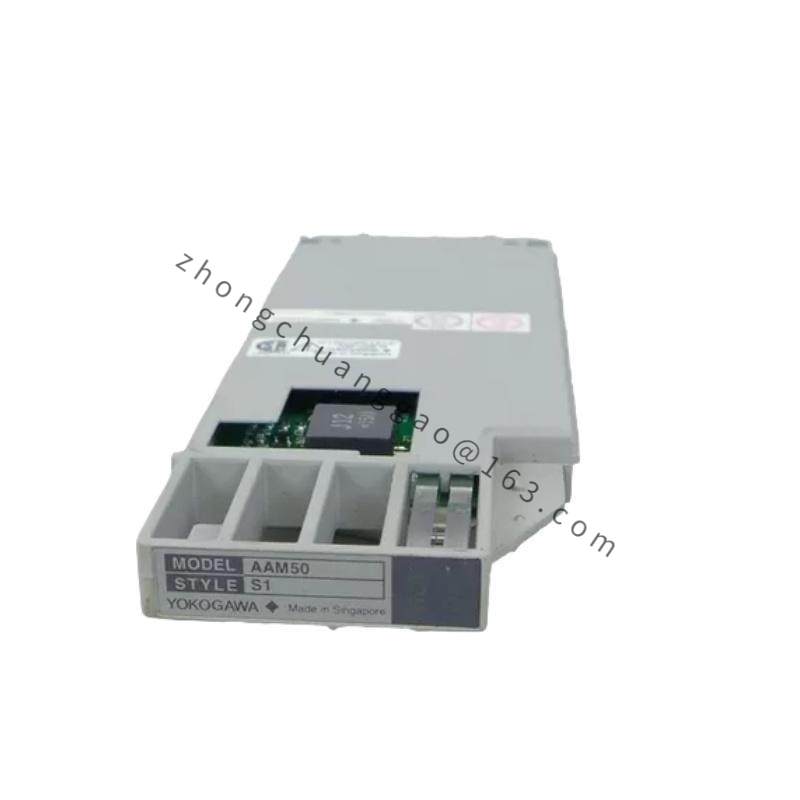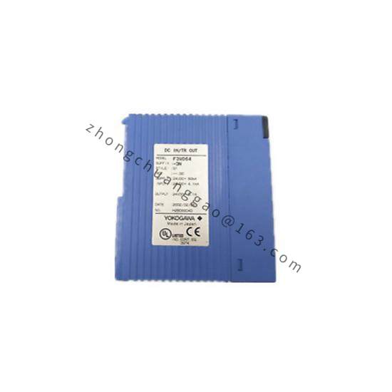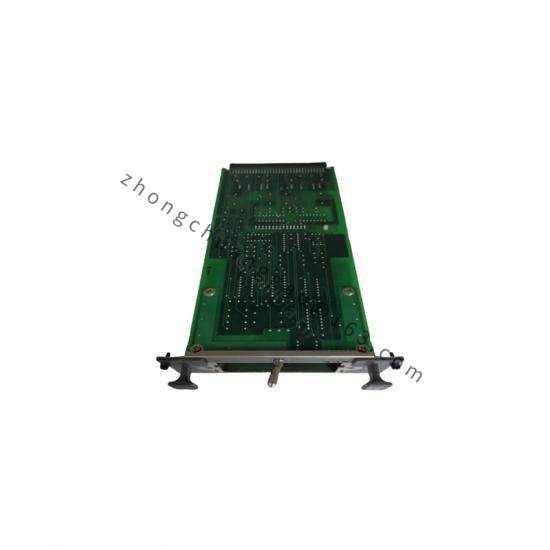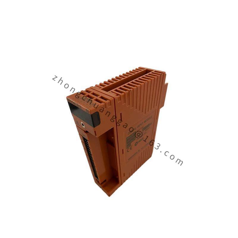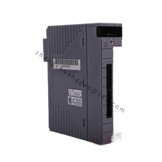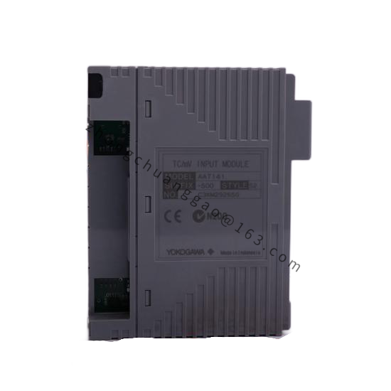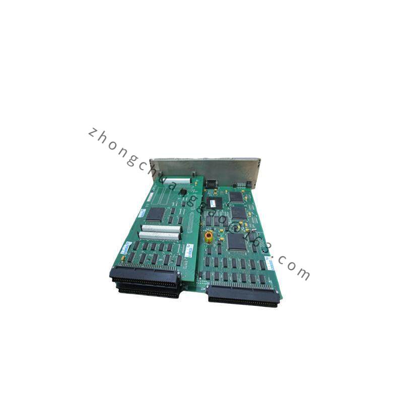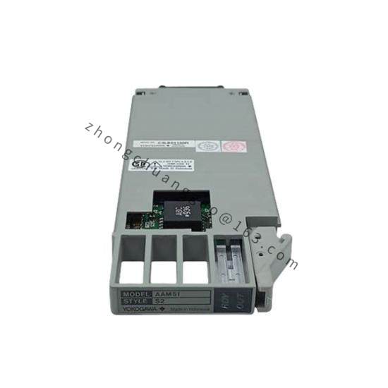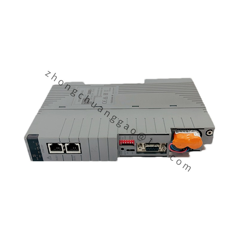


YOKOGAWA F3AD08-6R
Product Series: F3/F4 Series PLC Analog I/O Modules
Product Introduction:
The F3AD08-6R is an 8-channel analog input module for the Yokogawa F3/F4 series PLC. It accepts 4–20 mA (2-wire) current signals from field transmitters and converts them to digital values for the PLC CPU to process.
Detailed content
Technical Specifications:
- Module Type: Analog Input (Current)
- Number of Channels: 8 channels
- Input Signal: 4–20 mA DC (2-wire transmitters)
- Input Impedance: 250 Ω (burden resistor built-in)
- Resolution: 12-bit (4096 steps)
- Conversion Accuracy: ±0.1% of Full Scale (FS)
- Sampling Time: 10 ms per channel (total scan: 80 ms for 8 channels)
- Common Mode Rejection Ratio (CMRR): ≥ 80 dB at 50/60 Hz
- Isolation Voltage: 500 VDC (channel-to-channel, channel-to-bus)
- Power Supply: 5 VDC from PLC backplane bus
- Current Consumption: 180 mA (typ.) from backplane
- Operating Temperature: 0°C to +55°C (+32°F to +131°F)
- Dimensions (W × H × D): 25 mm × 90 mm × 85 mm
- Weight: Approximately 0.1 kg
Functional Features:
- 8 independent channels with individual scaling (engineering units, range, damping)
- Built-in 250 Ω burden resistor — no external resistor required for 2-wire transmitters
- Channel-to-channel isolation prevents ground loop interference
- On-line module replacement (hot-swap capable in F4 series)
- LED indicators per channel for signal presence detection
Structural Features:
- Standard F3/F4 module form factor
- DIN rail mountable in PLC rack
- Screw-terminal block connector for all 8 input channels (2 wires per channel: + and -)
- Isolation barrier between field side and bus side
Working Principle:
Each of the 8 input channels receives a 4–20 mA signal from a 2-wire field transmitter. The current flows through the built-in 250 Ω burden resistor, developing a 1–5 VDC voltage proportional to the current. This voltage is fed to a 12-bit A/D converter. The digital result is scaled to engineering units (e.g., °C, PSI, %) using parameters set in the PLC CPU and stored in the module’s register. The isolated digital data is transferred to the CPU via the backplane bus.
Advantages & Highlights:
- Built-in 250 Ω burden eliminates external components — reduces wiring and cost
- 12-bit resolution provides fine measurement granularity (4096 steps)
- ±0.1% FS accuracy meets most process control requirements
- Channel isolation eliminates cross-talk and ground loop errors
- 8 channels in one module — reduces rack space and cost vs. single-channel modules
Applicable Industries:
- Chemical process control
- Oil and gas (wellhead, pipeline monitoring)
- Water and wastewater (flow, level, pressure)
- Power plant (temperature, pressure, flow)
- Food and pharmaceutical (batch control)
Installation Requirements:
- Insert into F3/F4 PLC rack at the designated slot
- Connect 2-wire transmitter loop: transmitter (+) to module input (+), transmitter (-) to module input (-)
- Use shielded twisted-pair cable for all analog inputs
- Connect the shield to earth ground at one end only (DCS/PLC side)
Usage Precautions:
- Do not apply voltage signals (0–10 V, 0–5 V) to current input terminals — will damage the module
- Maximum loop resistance (transmitter + wiring) must not exceed 600 Ω at 24 VDC supply
- Do not leave input channels unconnected — floating inputs cause erratic readings
- Perform zero calibration (4 mA = 0%, 20 mA = 100%) after installation