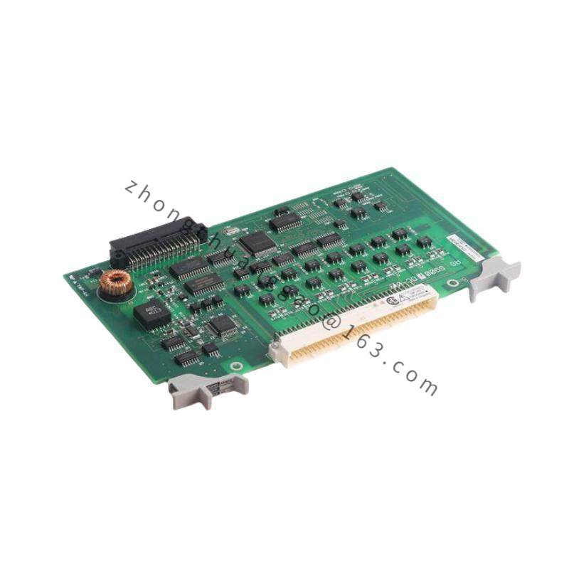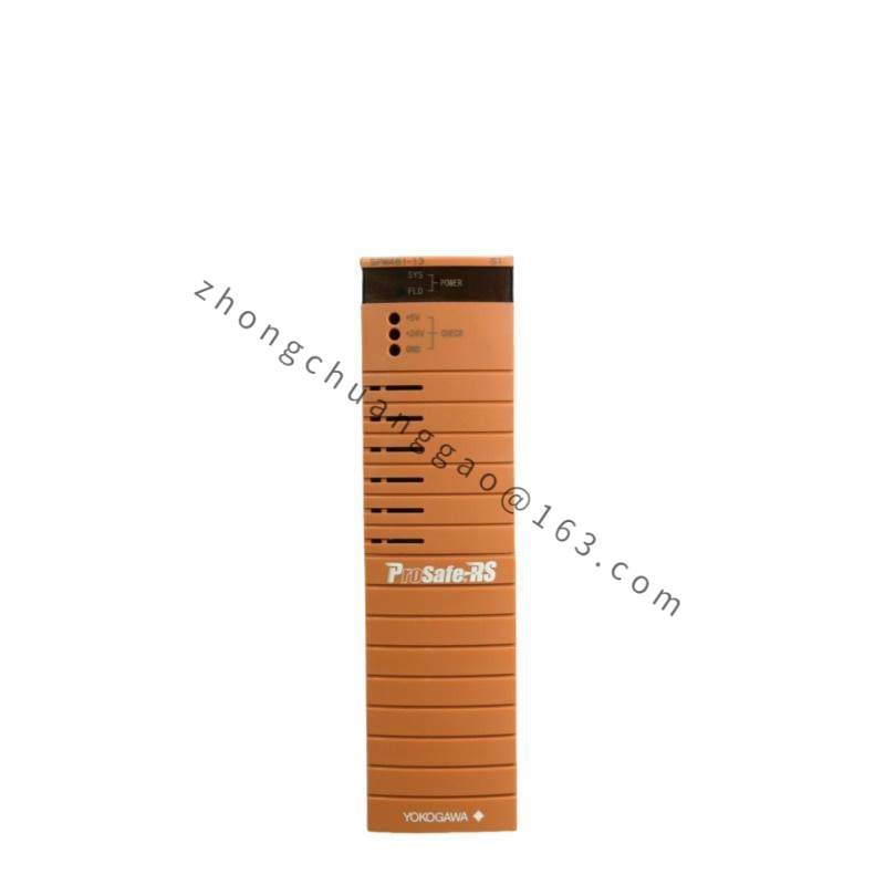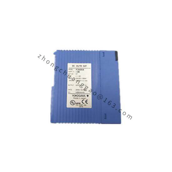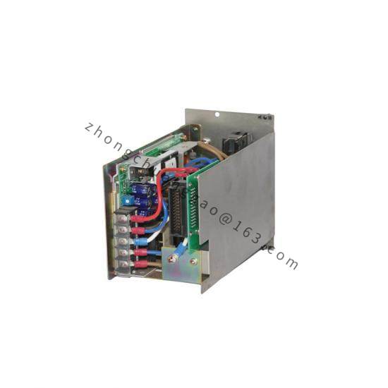


YOKOGAWA EB401-50
Product Introduction:
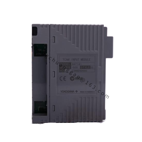
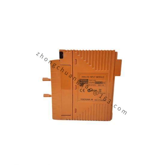
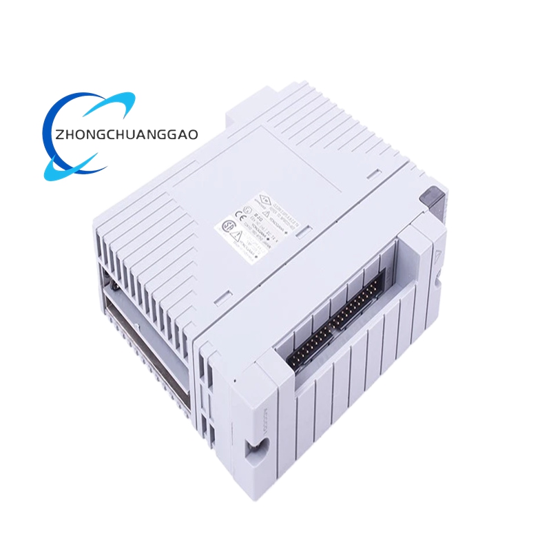
The EB401-50 is a 4-channel analog input module for the Yokogawa F3 and FA-M3 Series Programmable Logic Controllers. This module accepts 4–20 mA DC current loop signals from field transmitters and converts them to digital values for the PLC CPU. The “50” suffix indicates the specific firmware/configuration variant for standard 4–20 mA input with basic scaling.
Detailed content
Technical Specifications:
- Number of Channels: 4 channels (independent)
- Input Signal: 4 to 20 mA DC (2-wire loop powered)
- Input Impedance: 250 Ω (burden resistor, converts mA to 1–5 V for A/D)
- A/D Resolution: 16-bit (65,536 steps)
- Input Range (scaled): 0 to 4000 counts (configurable engineering units)
- Accuracy: ±0.1% of span (typical), ±0.2% of span (worst case)
- Scan Time: 10 ms per module (all 4 channels)
- Isolation: 500 V DC between channels, 500 V DC between field and bus
- Power Consumption: ≤1.5 W per module
- Operating Temperature: 0°C to +55°C
- Compliance: CE, UL 508
Functional Features:
- Each channel supports independent engineering unit scaling (e.g., Channel 1 = 0–100°C, Channel 2 = 0–10 bar)
- Input break detection — configurable alarm when signal drops below 3.6 mA (fail-low) or above 21 mA (fail-high)
- Digital filtering — configurable moving average (1 to 64 samples)
- LED indicators per channel: Power (green), Input OK (green), Alarm (red)
Performance Parameters:
| Parameter | Value |
|---|---|
| Linearity | ±0.05% of span |
| Temperature Coefficient | ±0.01% of span per °C (0–55°C) |
| Common Mode Rejection | ≥80 dB at 50/60 Hz |
| Max Loop Resistance | 600 Ω at 24 V DC supply |
| Data Update Rate | 100 ms (10 Hz) per channel |
Material Composition:
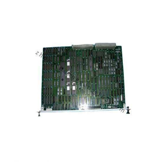
- PCB: FR-4, 4-layer, with conformal coating (silicone type)
- Housing: Flame-retardant PBT plastic (UL 94 V-0)
- Terminals: Phoenix Contact-compatible, spring-clamp, 2.5 mm² max wire
- Connector (bus side): F3/FA-M3 standard backplane connector, 48-pin
Structural Characteristics:
- Form Factor: F3/FA-M3 standard module
- Dimensions: 98 mm (W) × 130 mm (H) × 90 mm (D)
- Weight: Approximately 0.25 kg
- Mounting: DIN rail or backplane insertion in F3/FA-M3 rack
Working Principle:
The 4–20 mA signal from each field transmitter flows through a precision 250 Ω burden resistor, generating a 1–5 V voltage proportional to the current. This voltage is amplified by an instrumentation amplifier with programmable gain, then digitized by a 16-bit successive approximation A/D converter. The digital value is transferred to the PLC CPU via the F3/FA-M3 backplane bus using a dedicated DMA (Direct Memory Access) controller for deterministic scan timing.
Key Advantages:
- 4 independent channels in a single module — saves rack space and cost
- ±0.1% accuracy — meets most process control requirements without external signal conditioners
- Input break detection — immediate alarm for wire fault conditions
- Fully compatible with F3 and FA-M3 PLC platforms — drop-in replacement for older modules
Applicable Industries:
- Water treatment (flow, level, pH transmitter interfacing)
- HVAC (temperature, humidity, CO2 monitoring)
- Food and beverage (tank level, flow totalization)
- Manufacturing (pressure, force, weight monitoring)
- Building automation (BMS sensor integration)
Installation Requirements:
- Insert into F3 or FA-M3 PLC rack (slot must be configured for analog input in engineering software)
- Wire 4–20 mA loops to spring-clamp terminals (positive to +, negative to − per channel)
- Do not exceed 600 Ω total loop resistance (including wire resistance)
- Configure channel scaling and alarm limits in F3/FA-M3 engineering software (FBM/Sysmac Studio)
Usage Precautions:
- Never apply voltage > 30 V DC to the mA input terminals — will destroy the burden resistor and A/D converter
- Verify loop power supply can deliver ≥25 mA per channel (4 channels × 20 mA = 80 mA total)
- Do not mix 4–20 mA inputs with voltage inputs on the same module — use dedicated modules for each signal type
- Store unused modules in anti-static bags at 0°C to +40°C